
Multiple Scattering Medium For Compressive Imaging

a scattering medium and compressive imaging technology, applied in the field of multiple scattering mediums for compressive imaging, can solve the problems of large amount of raw data generated by a large detector array that can require immediate compression, high cost and complexity of each detector,

Inactive Publication Date: 2015-02-05
CENT NAT DE LA RECHERCHE SCI +2
View PDF4 Cites 14 Cited by
  • Summary
  • Abstract
  • Description
  • Claims
  • Application Information

AI Technical Summary

Benefits of technology

This patent describes a method and system for estimating the image of an optical, electromagnetic, or acoustic signal using a multiple scattering medium. The method involves scattering the incident signal into the medium, measuring the scattered signals using a detector array, and determining the estimated image using a processor. The estimated image has a greater number of elements than the number of measurements. The system includes a memory that stores a known transmission matrix of the medium and a processor that determines the estimated image from the measurements and the transmission matrix. The method and system can be used in various imaging applications.

Problems solved by technology

First, the cost and complexity of each detector can be quite high, especially when it comes to imaging wavelengths of electromagnetic radiation that lies outside the scope of CCD or CMOS detectors.
In some cases, the usage of many detectors is actually impossible or impractical.
Second, the huge amount of raw data generated by a large detector array can require immediate compression in order to transmit or store data.
This compression is computationally demanding while it can be difficult to provide computational resources inside the limited size of an imaging device.
It consumes power and is often expensive, complex and brittle.
The acquisition of a series of measurements also slows down the process as it requires time-multiplexing.
Furthermore, the complexity of the detection system, more specifically its number of pixels, has not in fact disappeared but was simply translated to a complexity of the optical modulator.
Eventually, the size of the system, having a DMD as the optical modulator, can be quite difficult to reduce given the need to reflect the incident image on the DMD.

Method used


Image

  • Multiple Scattering Medium For Compressive Imaging
  • Multiple Scattering Medium For Compressive Imaging
  • Multiple Scattering Medium For Compressive Imaging

Examples


Embodiment Construction

1. Compressed Sensing

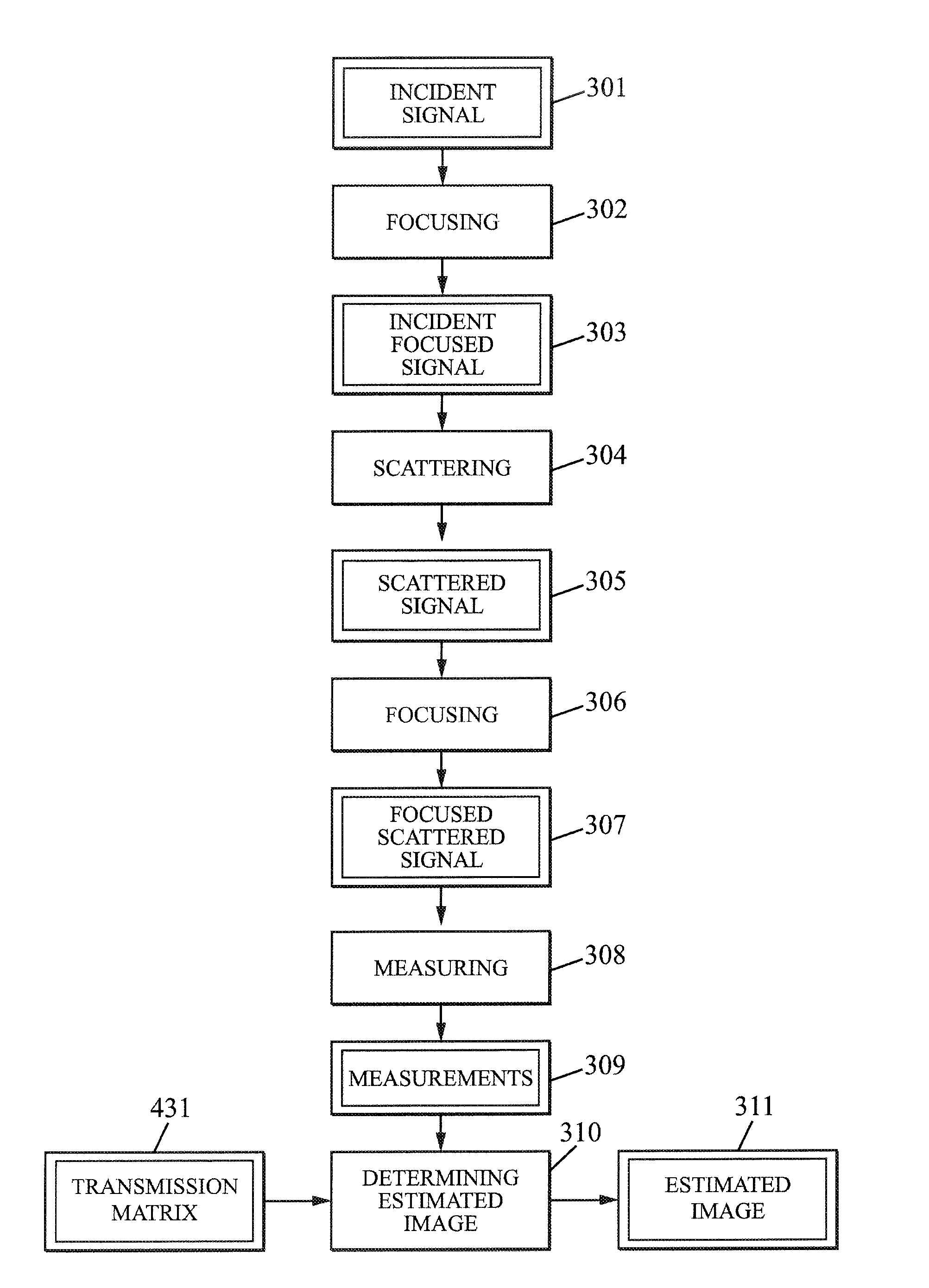
[0049]The Compressed Sensing theory intends to characterize a signal with fewer measurements than by the standard Shannon-Nyquist regular sampling theory. A defining characteristic of Compressive Sensing is that less than one measurement is needed per estimated signal value; a N-sample image can be reconstructed at full spatial bandwidth from M<N measurements. In the following, the expression “element of information” is used as a generic expression for “samples”, “pixels at full resolution” or “elements of images”.

[0050]The possibility to recover signal from incomplete information comes from the uses of sparsity or compressibility of an image model. Most commonly acquired images do not consist in random sets of data but rather in organized ones, meaning that there exists some basis, frame or dictionary in which these images have a concise representation. The mathematical equivalent to this concise representation consists in saying that the image or signal x can ...


PUM


Abstract

A method for estimating an optical, electromagnetic or acoustic image having at least the successive steps of: scattering an incident optical, electromagnetic or acoustic signal using a multiple scattering medium corresponding to a known transmission matrix stored into a memory of an imaging system; measuring the scattered signal using a detector array and storing the measurements into the memory of the imaging system; and determining an estimated image having a number of image elements that is greater than the number of measurements, at full spatial bandwidth. The estimated image is determined from the measurements and the transmission matrix using a sparsity-promoting algorithm.

Description

FIELD OF THE INVENTION[0001]The instant invention relates to systems and methods for estimating optical, electromagnetic or acoustic images using less than one measurement per estimated signal value of the estimated image.BACKGROUND OF THE INVENTION[0002]Imaging and visualization devices are typically constituted of an optical assembly of lenses and / or mirrors followed by an array of detectors. The number of elements of this array is traditionally related to the resolution of the acquired image and thus should be as large as possible in most applications.[0003]Nevertheless, a large array of detectors can have two major shortcomings. First, the cost and complexity of each detector can be quite high, especially when it comes to imaging wavelengths of electromagnetic radiation that lies outside the scope of CCD or CMOS detectors. In some cases, the usage of many detectors is actually impossible or impractical. Second, the huge amount of raw data generated by a large detector array can ...

Claims


Application Information

Patent Timeline
IPC IPC(8): H04N5/335H04N5/225G02B5/02H04N3/02
CPCH04N5/335G02B5/0273H04N5/2254H04N3/02G06T11/006G06T2211/424H04N25/00
Inventor GIGAN, SYLVAINLEROSEY, GEOFFROYDAUDET, LAURENTCHARDON, GILLESPOPOFF, SEBASTIENCARRON, IGOR
Owner CENT NAT DE LA RECHERCHE SCI
Learn More