Battery cooling fan mounting

a technology for cooling fans and mounting brackets, which is applied in the direction of batteries, cell components, battery/cell propulsion, etc., can solve the problems of not being able to push the fan assembly into the batteries, and achieve the effect of minimizing the risk simple mounting of the cooling fan assembly, and quick

Inactive Publication Date: 2015-02-05
FORD GLOBAL TECH LLC
View PDF4 Cites 9 Cited by
  • Summary
  • Abstract
  • Description
  • Claims
  • Application Information

AI Technical Summary

Benefits of technology

[0005]An advantage of an embodiment is that the cooling fan assembly for the battery-pack may be mounted in the vehicle directly behind the battery-pack, while minimizing a risk of the cooling fan assembly, and especially the motor unit, from damaging battery-pack internal components during a vehicle rear impact event. This allows for flexibility in locating the cooling fan assembly taking into account packaging, weight, and efficiency constraints. Moreover, the mounting of the cooling fan assembly is relatively simple, quick, while still allowing for the desired functionality during a vehicle rear impact event.

Problems solved by technology

While it may be desirable from a packaging and cooling efficiency standpoint to locate the cooling fan assembly right next to the batteries, it is not desirable to have the fan assembly pushed into the batteries during a vehicle impact event.
However, for some vehicles, it may be difficult due to packaging constraints or possibly less efficient for cooling to locate the cooling fan assembly offset from the batteries.

Method used


Image

  • Battery cooling fan mounting
  • Battery cooling fan mounting
  • Battery cooling fan mounting

Examples


Embodiment Construction

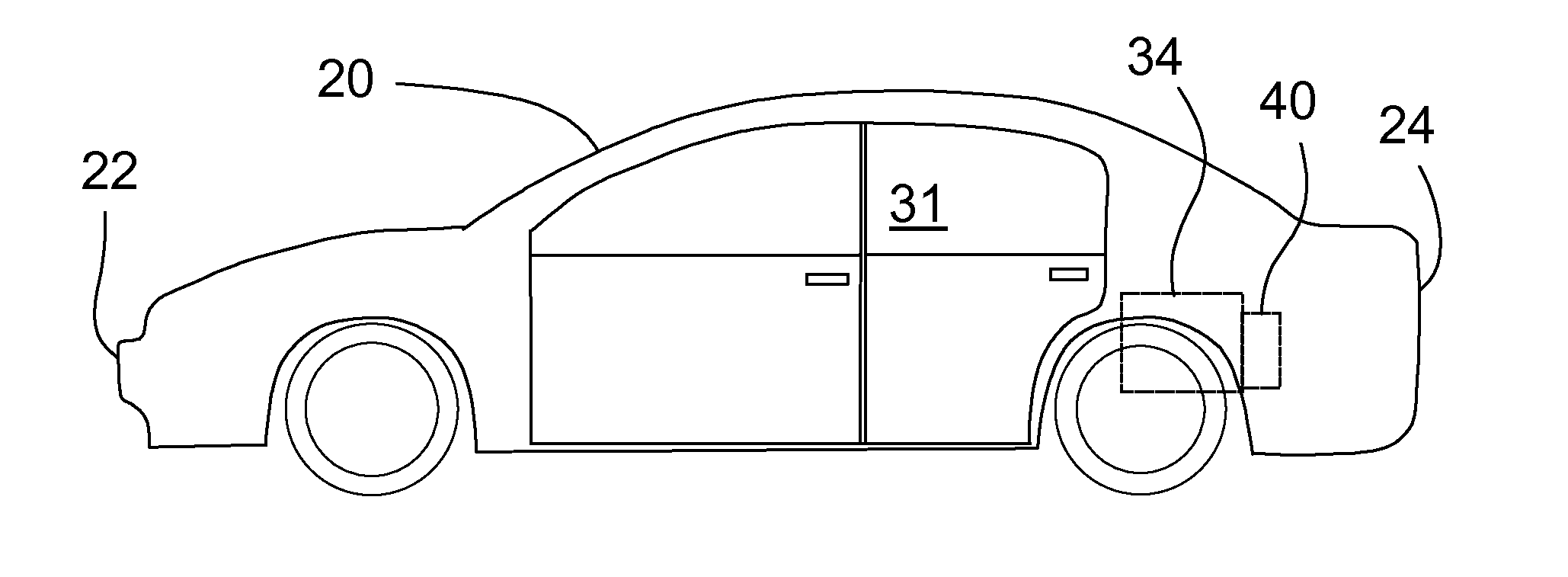
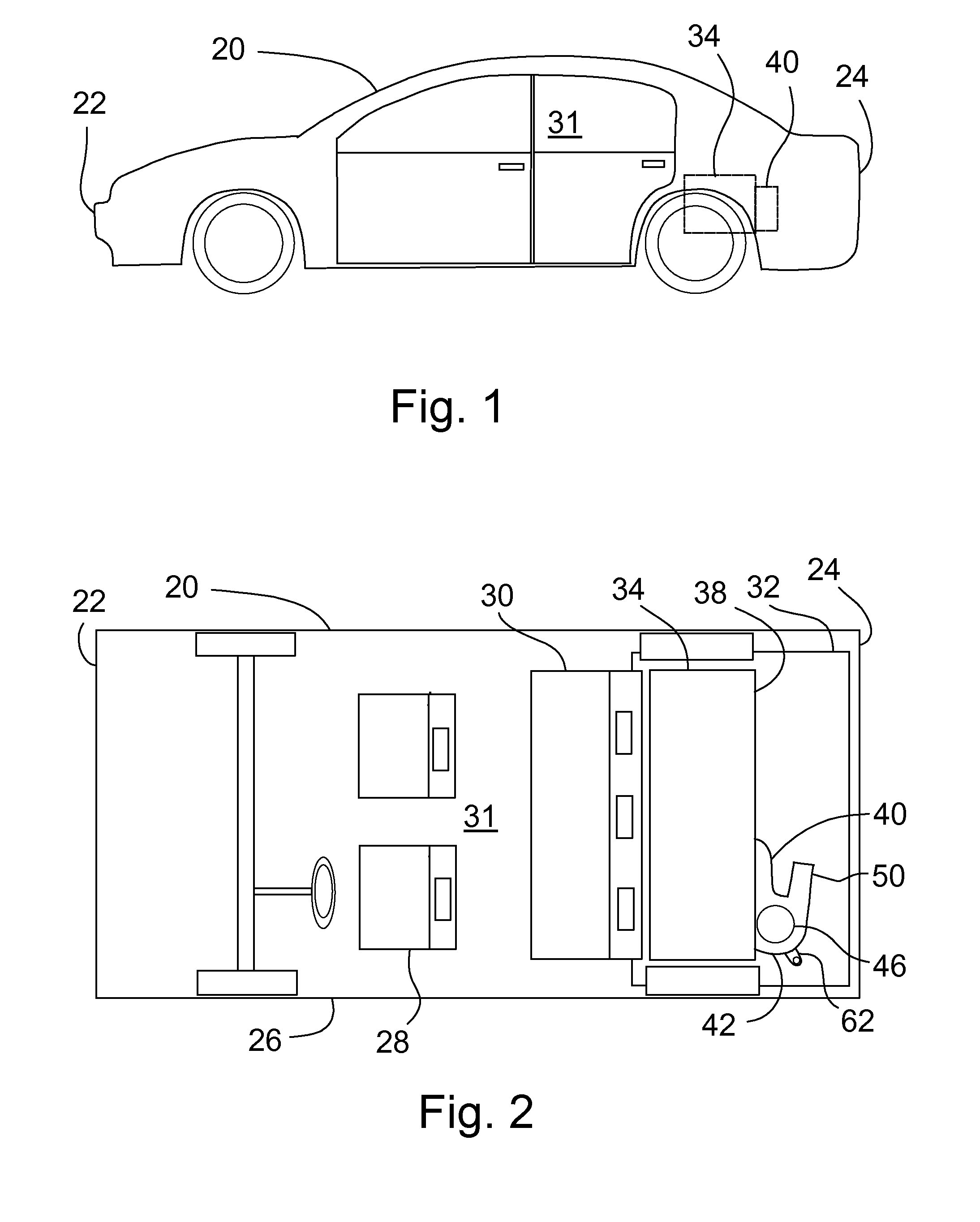
[0012]FIGS. 1 and 2 show an automotive vehicle 20 having a front end 22 and a rear end 24, as well as two sides 26. The vehicle 20 includes front seats 28 and rear seats 30 in a passenger compartment 31. A rear portion of a floor 32 is located behind the rear seats 30 and extends between the sides 26 to the rear end 24 of the vehicle 20.

[0013]Mounted above the floor 32, behind the rear seats 30 is a battery-pack 34. The term battery-pack, as used herein, may include other electronic components, such as power electronics, in addition to the actual battery cells themselves (not shown). A housing 36 of the battery-pack 34 includes a rear wall 38 that includes fluid flow openings that correspond to fluid flow openings in a cooling fan assembly 40.

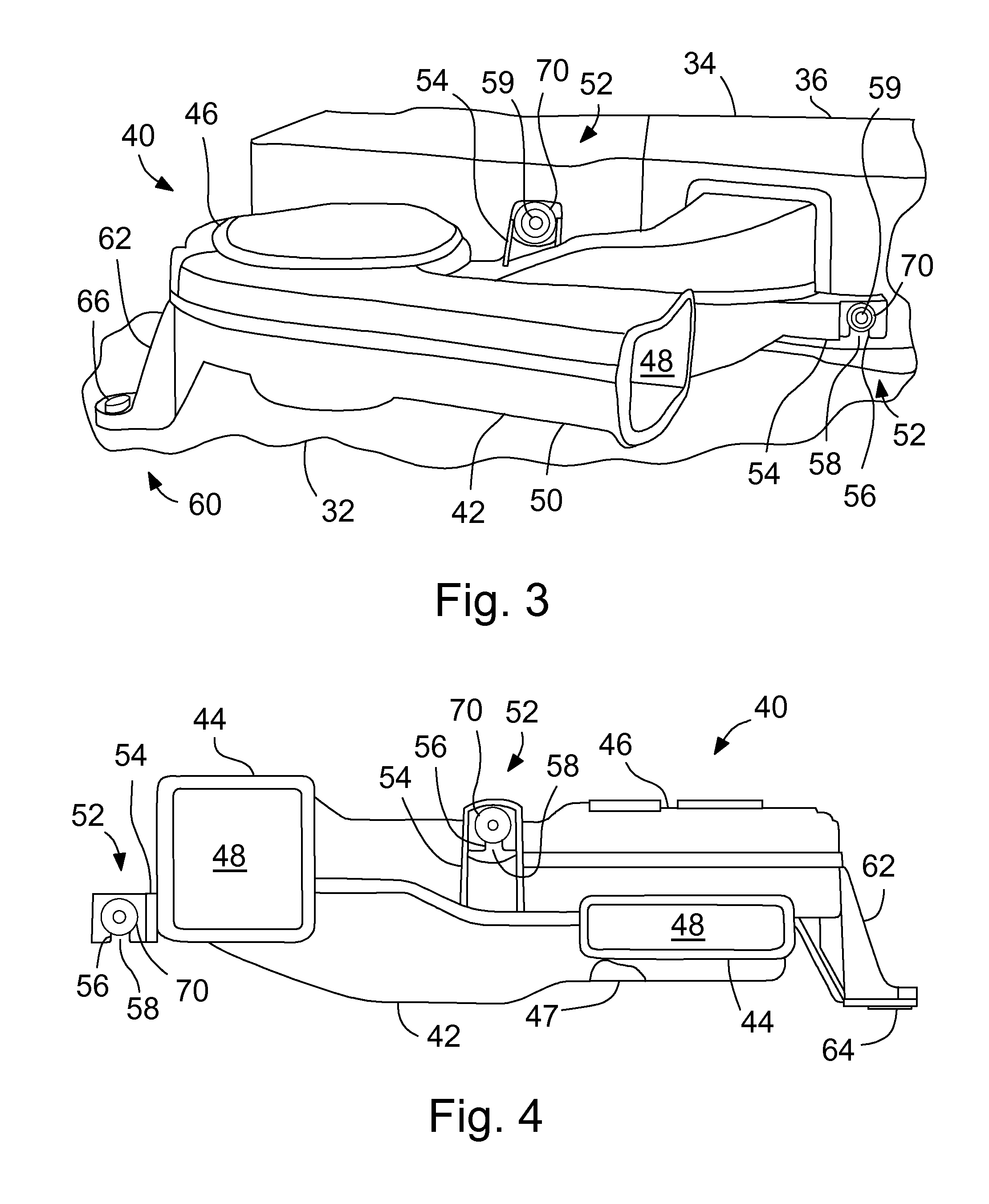
[0014]The cooling fan assembly 40 will now be discussed relative to FIGS. 1-6. The cooling fan assembly 40 includes a fan housing 42. The fan housing 42 may be formed from plastic, or other suitable material. A pair of front ducts 44 include op...


PUM

PropertyMeasurementUnit
temperatureaaaaaaaaaa
vehicle structureaaaaaaaaaa
flexibilityaaaaaaaaaa

Abstract

A vehicle having: vehicle structure including a pair of opposed sides and a rear, with a floor extending horizontally between the sides and rear; a battery-pack mounted above the floor; a fan assembly having a housing with a motor mounted therein directly behind the battery-pack, with the housing including a pair of flanges having U-slots with slot openings facing downward; and fasteners extending horizontally through the U-slots and secured to the battery-pack.

Description

BACKGROUND OF INVENTION[0001]The present invention relates to a vehicle battery pack assembly, and more particularly to the mounting of a fan assembly that cools the battery pack.[0002]In vehicles that employ batteries for propulsion, such as for example, hybrid electric or battery electric vehicles, the batteries are often located behind the rear seats in a rear cargo area. The battery system may include a cooling fan assembly that creates a cooling flow inside the battery to maintain the desired battery temperature. While it may be desirable from a packaging and cooling efficiency standpoint to locate the cooling fan assembly right next to the batteries, it is not desirable to have the fan assembly pushed into the batteries during a vehicle impact event.[0003]Accordingly, some have mounted the cooling fan motor and that portion of the cooling fan assembly offset laterally to the side of the batteries. In this way, in a vehicle rear impact event, the fan motor likely will not be pu...

Claims


Application Information

Patent Timeline
Patent Type & Authority Applications(United States)
IPC IPC(8): H01M10/613H01M10/625H01M10/6556H01M10/6563
CPCH01M10/5004H01M10/5067H01M2220/20H01M10/5057H01M10/5016B60L50/64H01M10/613H01M10/625H01M10/6556H01M10/6563Y02E60/10Y02T10/70
Inventor JANARTHANAM, SURIYAPRAKASH A.KIMOTO, MASAHIRO
Owner FORD GLOBAL TECH LLC
Why Eureka
Try Eureka