SAR Point Cloud Generation System

a generation system and point cloud technology, applied in the field of sar point cloud generation system, can solve the problems of inability to robustly repair, inability to accurately determine the elevation of the phase, and inability to accurately measure the noise of the phase measurement, so as to reduce the cost of the multi-aperture system, efficient collection and accurate, and high data quality

Active Publication Date: 2015-02-12
GENERAL ATOMICS
View PDF0 Cites 26 Cited by
  • Summary
  • Abstract
  • Description
  • Claims
  • Application Information

AI Technical Summary

Benefits of technology

[0017]A particularly valuable augmentation to this process involves combining several independently derived SAR point clouds of a target as viewed from different aspect angles, or azimuths. Since many 3D structures, particularly manmade structures, have radar responses that are highly dependent on the viewing angle, a combination of geometrically diverse point clouds provides a much more detailed and complete representation of the target. These multiple aspect views may be obtained in a deliberate manner by collecting the SAR data along a circular path such that the imaged area of interest is always viewed. Repeated circles provide the sparse aperture needed for the SPC product derivation at each azimuth angle. A similar product can be generated from linear (non-circular) acquisitions also if appropriate lines are flown. This linear approach provides the ability to acquire multi-aspect SPC products from systems that cannot execute circular collections, such as a spacebor

Problems solved by technology

The separation therefore must be large enough to produce a measurement of radar phase differences that may be usefully converted into terrain heights, but not so large as to become incoherent making phase measurements very noisy and accurate elevation determination impossible.
A related and limiting issue involves what are known as height ambiguities.
In the case where there are such discontinuities, InSAR elevation estimates will be in error by some multiple of the height ambiguity, and this error will propagate throughout the scene due to the unwrapping process.
Some techniques for identifying ambiguity errors have been developed, but no methods for their robust repairs are possible (Ghiglia and Pritt).
Various unwrapping approaches have been developed (e.g. Least-Squares approach as described by Ghiglia et al. in U.S. Pat. No. 5,424,743), that mi

Method used


Image

  • SAR Point Cloud Generation System
  • SAR Point Cloud Generation System
  • SAR Point Cloud Generation System

Examples


Embodiment Construction

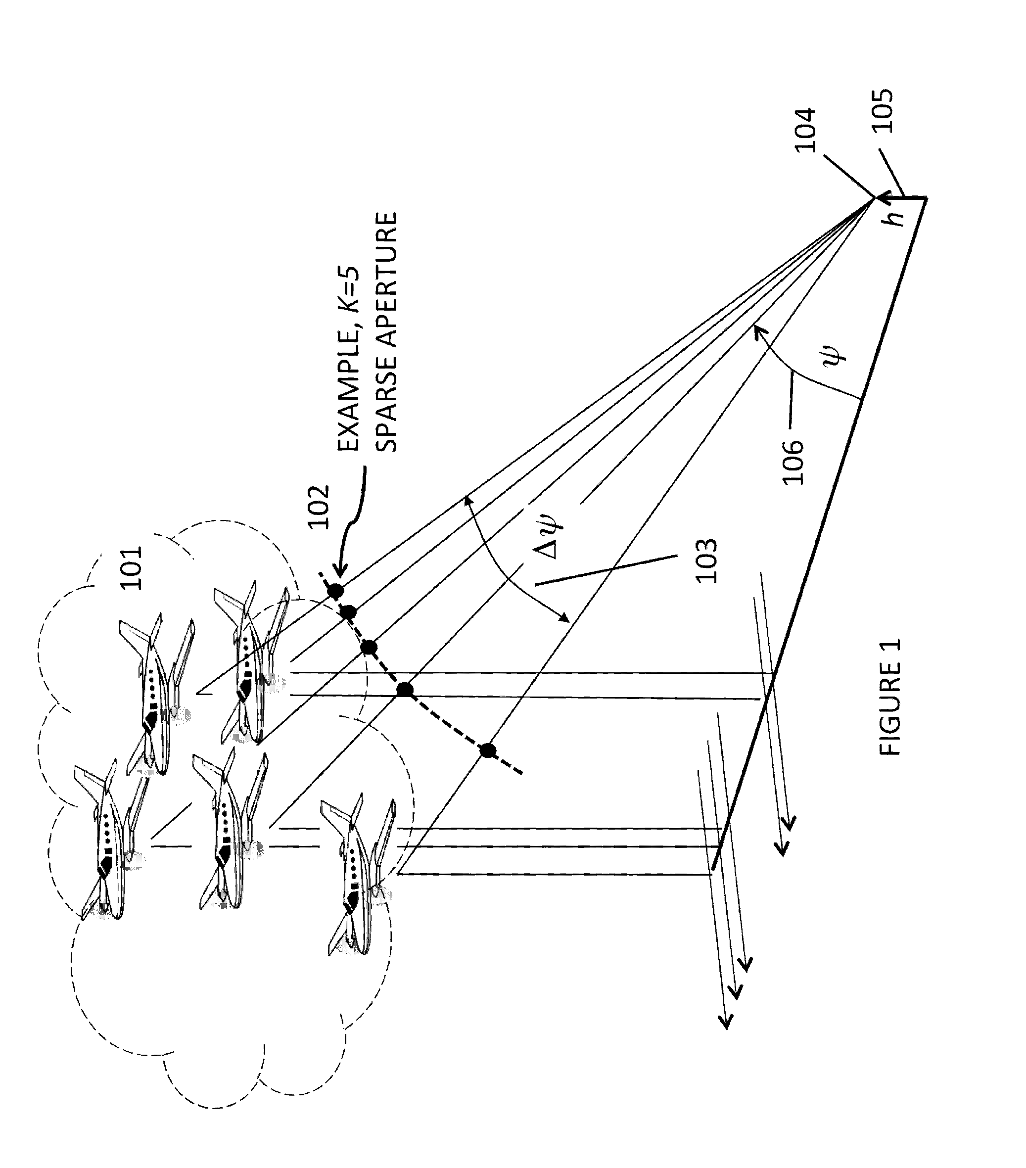
[0031]Referring to the drawing figures, FIG. 1 shows one version of a SAR Point Cloud collection system. Individual SAR systems flown in aircraft 101 (with suitable geometry as will be described herein) image to the side using synthetic aperture radar technology. The ensemble of SAR data acquired by the individual SAR systems, which may be acquired at the same time or at different times, form a sparse imaging aperture 102 which may be considered the input to the present invention. A geometric constraint such that the full angle 103 subtended by the sparse aperture from a point on the ground 104 elevated a distance h 105 above a reference plane, is well within a maximum angle required to maintain spatial coherence of the SAR echoes,

Δψmax=λ2ρg1sin(ψ),

where ρg is the SAR resolution on the ground plane and ψ106 is the average graze angle of all the SAR systems to the point on the ground. While it is possible to utilize the present invention with data acquired with larger apertures than ...


PUM


Abstract

The SAR Point Cloud Generation System processes synthetic aperture radar (SAR) data acquired from multiple spatially separated SAR apertures in such a manner as to be able to calculate accurate three-dimensional positions of all of the scatterers within the imaged scene. No spatial averaging is applied thus preserving the high resolution of the original SAR data, and no phase unwrapping processes are required. The effects of height ambiguities are significantly reduced in the SAR Point Cloud Generation System. The SAR Point Cloud Generation System also self-filters against mixed-height pixels that can lead to incorrect height estimates. The system estimates scatterer height by a maximization of an Interferometric Response Function.

Description

BACKGROUND OF THE INVENTION[0001]1. Field of the Invention[0002]This invention relates to the field of using remote radar systems for mapping terrain and structures found on the terrain in three dimensions.[0003]2. Description of the Related Art[0004]Synthetic Aperture Radar (SAR) was invented as a military reconnaissance instrument in the 1950's and further developed through the 1960's as a way to image ground terrain at high resolution, typically from an aircraft. It had advantages over passive optical reconnaissance systems since it could operate at night and see through clouds. Furthermore, due to the nature of SAR imaging techniques, the sensor could operate at very large standoff distances without sacrificing resolution. During the early 1970's interferometric SAR systems were invented. In such systems, the phase difference of the radar echoes received at two antennas spaced perpendicular to the aircraft's velocity vector are used to estimate the elevation angle from the SAR t...

Claims


Application Information

Patent Timeline
IPC IPC(8): G01S13/90
CPCG01S13/9023G01S13/90G01S13/9035G01S13/904
Inventor CARANDE, RICHARD E.COHEN, DAVID
Owner GENERAL ATOMICS
Why Eureka
Try Eureka