Blade cascade and turbomachine

Active Publication Date: 2015-02-12
MTU AERO ENGINES GMBH
View PDF12 Cites 13 Cited by
  • Summary
  • Abstract
  • Description
  • Claims
  • Application Information

AI Technical Summary

Benefits of technology

[0004]It is an object of the present invention to provide a blade cascade of a turbomachin

Problems solved by technology

Since, due to the lower velocity thereof, flow layers proximal to the wall are deflected to a greater degree than flow layers distal to the wal

Method used


Image

  • Blade cascade and turbomachine
  • Blade cascade and turbomachine
  • Blade cascade and turbomachine

Examples


Example

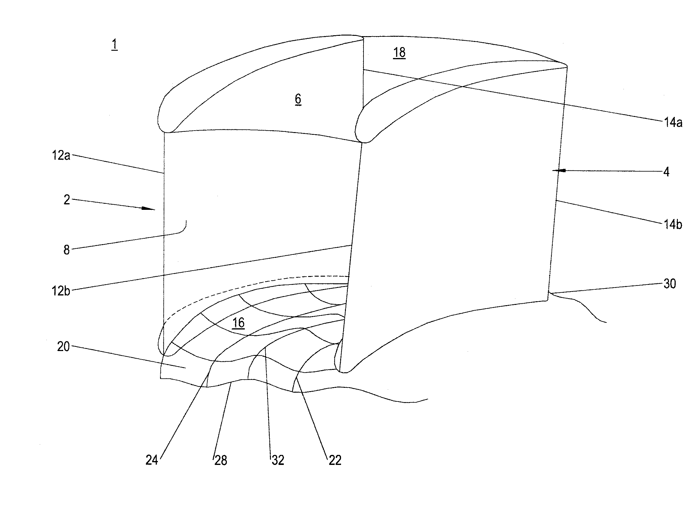
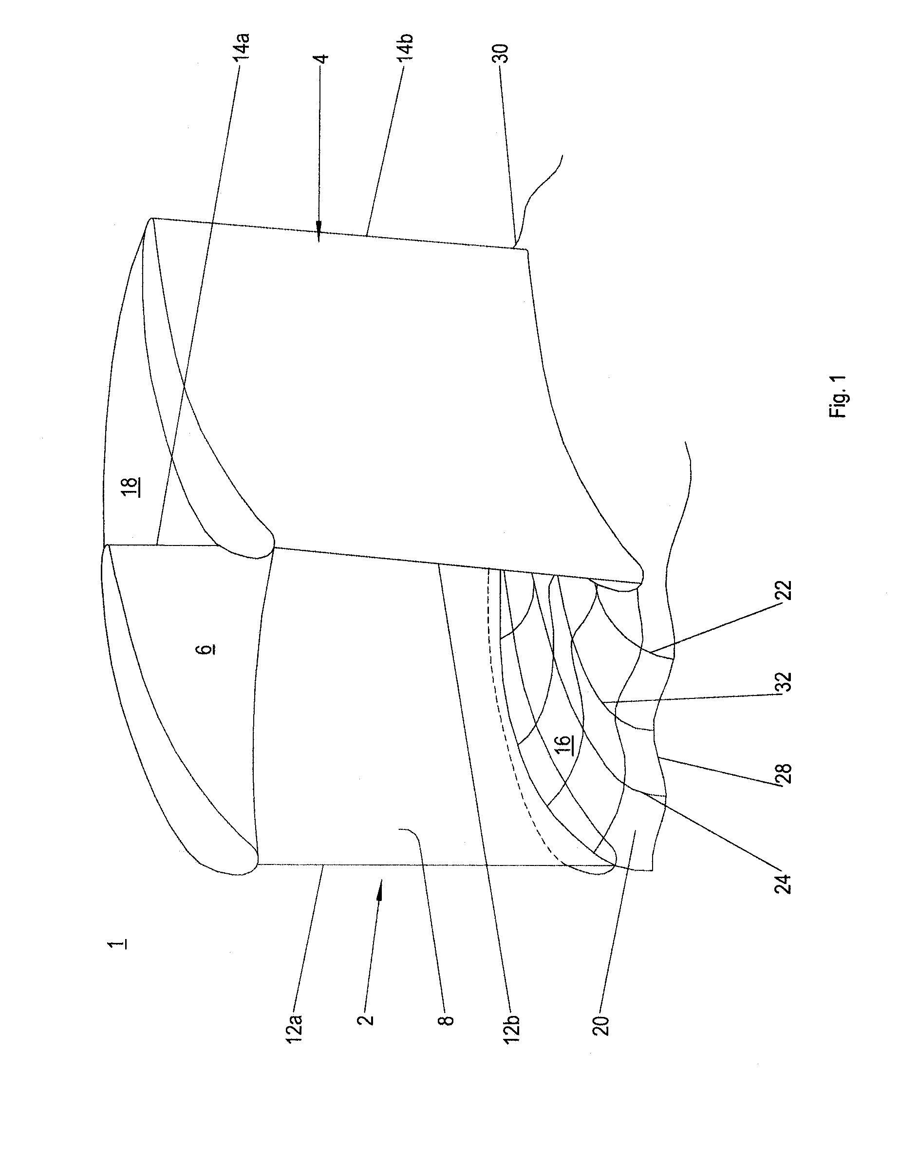
[0022]FIG. 1 shows a perspective front view of a blade channel of a first exemplary embodiment of a blade cascade 1 according to the present invention of an axial turbomachine, such as a stationary gas turbine or an aircraft engine.

[0023]Blade cascade 1 is preferably configured on the turbine side and has a plurality of blades 2, 4 that are configured side-by-side in the circumferential direction of the turbomachine and each define a blade channel 6, which, in accordance with the representation in FIG. 1, is traversed from the front to the back, respectively from left to right by a main flow. In the circumferential direction of the turbomachine, respectively of blade cascade 1, blade channel 6 is bounded by a pressure side wall, respectively pressure side 8 of first blade 2 and by an opposite suction side wall, respectively suction side 10 of second blade 4. Suction side 10 is not visible in the perspective view in FIG. 1. Pressure side 8 and suction side 10 each extend between a le...


PUM


Abstract

A blade cascade of a turbomachine whose at least one side wall is configured to be circumferentially undulated and which has at least two elevations and at least one depression or at least two depressions having at least one elevation, as well as a turbomachine having a blade cascade of this kind.

Description

[0001]This claims the benefit of European Patent Application EP 131 793 49.9, filed Aug. 6, 2013 and hereby incorporated by reference herein.[0002]The present invention relates to a blade cascade of a turbomachine and to a turbomachine having such a blade cascade.BACKGROUND[0003]A primary, respectively main flow directed through a flow channel is deflected by a lateral pressure gradient parallel to the bounding wall. Since, due to the lower velocity thereof, flow layers proximal to the wall are deflected to a greater degree than flow layers distal to the wall, a secondary flow, respectively a channel vortex forms that is superimposed on the main flow, thereby leading, inter alia, to pressure losses. Such secondary flows regularly occur in blade cascades of turbomachines, such as gas and steam turbines. The blade cascades are composed of a plurality of circumferentially side-by-side disposed blades, respectively blades that are configured in an axially symmetrical flow channel and be...

Claims


Application Information

Patent Timeline
IPC IPC(8): F01D5/14F01D9/02
CPCF01D9/02F01D5/142F01D5/143F01D5/145F05D2250/611F05D2250/712F05D2250/711Y02T50/60
Inventor GIER, JOCHENGUENDOGDU, YAVUZENGEL, KARL
Owner MTU AERO ENGINES GMBH
Why Eureka
Try Eureka