Connector Terminal and Electric Connector
a technology of connecting terminals and connectors, which is applied in the direction of coupling contact members, coupling device connections, securing/insulating coupling contact members, etc., can solve the problems of poor connection, difficult matching of impedances, and inability to meet impedances, so as to facilitate impedance matching, prevent poor connection, and increase the impedance
- Summary
- Abstract
- Description
- Claims
- Application Information
AI Technical Summary
Benefits of technology
Problems solved by technology
Method used
Image
Examples
first embodiment
FIGS. 1 to 7
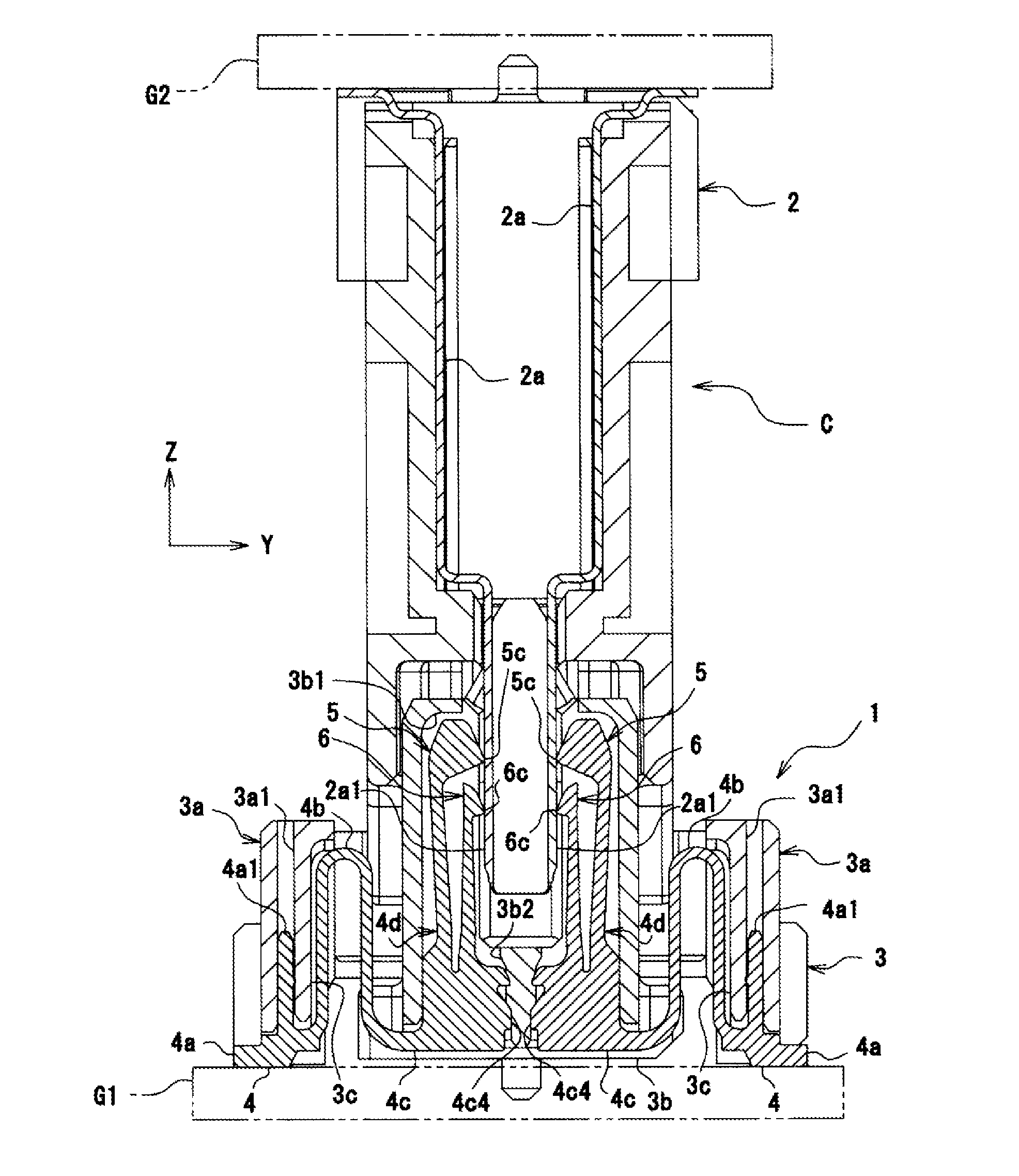
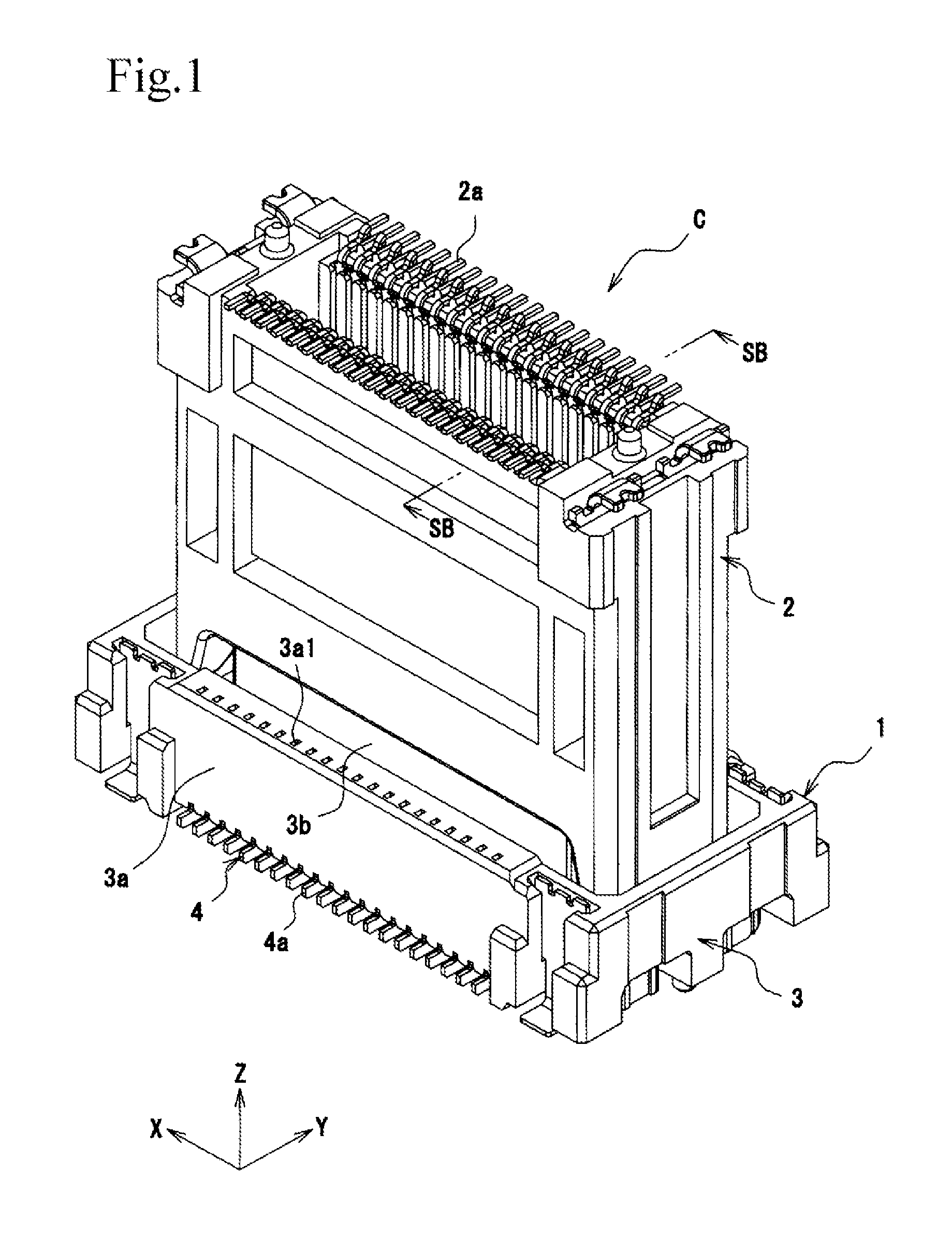
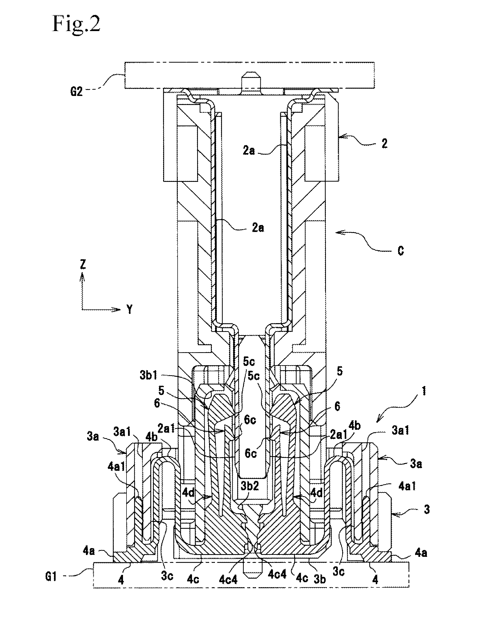
[0048]An electric connector C of the first embodiment according to the present invention includes a socket 1 and a plug 2. As shown in FIG. 2, the socket 1 is secured to a circuit board G1. As shown in FIG. 1, by fitting the socket 1 to the plug 2 (serving as a “mating connector”), the circuit board G1 and a circuit board G2 to which the plug 2 is secured are conductively connected with each other.
[0049]As shown in FIGS. 1 and 2, the socket 1 includes a substantially rectangular parallelepiped socket housing 3 and socket terminals 4 that are conductively connected with plug terminals 2a.
Socket Housing
[0050]The socket housing 3 is formed of insulating resin. As shown in FIGS. 1 and 2, the socket housing 3 includes a stationary housing 3a and a movable housing 3b that is displaceable relative to the stationary housing 3a by the socket terminals 4. The stationary housing 3a is provided with stationary holes 3a1 to which the socket terminals 4 are secured. The movable housi...
second embodiment
FIGS. 8 to 10
[0072]In the first embodiment, each socket terminal 4 is one in which the plate surface of its corresponding base end portion 4c has a substantially square shape. However, as shown in FIG. 8, each socket terminal 8 may be one in which a plate surface of a base end portion 7 has a substantially rectangular shape that is long along a short-side direction of a socket 1. FIG. 9 shows a socket terminal 8, with a length L1 in a width direction being on the order of 5 mm, a height L2 of a terminal portion 4d being on the order of 5 mm, a height L3 of a base end portion 7 being approximately 0.6 mm, and a distance L4 between the base end portion 7 and the terminal portion 4d being approximately 0.87 mm. FIG. 10 is a graph of a waveform of impedance measured at the socket terminal 8. According to FIG. 10, the waveform has a linear form whose difference between impedances is less than that of the waveform of the impedance measured at the socket terminal 4. Therefore, by bringing ...
third embodiment
FIG. 11
[0076]In the first and second embodiments, the socket terminals 4 and 8 including smooth, flat base end portions 4c and 7, respectively, are provided. In contrast, as shown in FIG. 11, it is possible to provide a socket terminal 12 having a through hole 11 that extends through a base end portion 4c along a plate thickness. By using such a socket terminal 12, the surface area of the base end portion 4c becomes small, so that a capacitor component is reduced. Therefore, it is possible to increase the impedances of portions beyond the base end portion 4c.
[0077]In the socket terminal 12, it is necessary to change the height of the base end portion 4c in accordance with a gap between a circuit board G2 and a circuit board G1 on which the socket terminal 12 is mounted. The larger the height of the base end portion 4c, the larger the capacitor component of a movable portion 4b. Since this causes a distance L4 between the movable portion 4b and a terminal portion 4d to be increased,...
PUM
 Abstract
Description
Claims
Application Information
 - R&D
- Intellectual Property
- Life Sciences
- Materials
- Tech Scout
- Unparalleled Data Quality
- Higher Quality Content
- 60% Fewer Hallucinations
Browse by: Latest US Patents, China's latest patents, Technical Efficacy Thesaurus, Application Domain, Technology Topic, Popular Technical Reports.
© 2025 PatSnap. All rights reserved.Legal|Privacy policy|Modern Slavery Act Transparency Statement|Sitemap|About US| Contact US: help@patsnap.com


