
Motor driven linear actuator and electric motor thereof

a linear actuator and motor technology, applied in the direction of toothed gearings, belts/chains/gearings, toothed gearings, etc., can solve the problem of weak rigidity of the coupling b>13/b>, and achieve the effect of reducing the space for coupling, accelerating rigidity, and reducing the force of the coupling

Active Publication Date: 2015-02-19
DELTA ELECTRONICS INC
View PDF11 Cites 12 Cited by
  • Summary
  • Abstract
  • Description
  • Claims
  • Application Information

AI Technical Summary

Benefits of technology

The present invention is about a motor driven linear actuator and its electric motor. The technical effect is that it allows for a rigid coupling and concentric locating between the motor shaft of the electric motor and the screw of the ballscrew device. This results in a more rigid actuator with faster response speed, smaller space requirement, and increased axial and radial rigidity of the electric motor.

Problems solved by technology

However, the rigidity of the coupling 13 is weak.

Method used


Image

  • Motor driven linear actuator and electric motor thereof
  • Motor driven linear actuator and electric motor thereof
  • Motor driven linear actuator and electric motor thereof

Examples


Embodiment Construction

[0019]The present invention will now be described more specifically with reference to the following embodiments. It is to be noted that the following descriptions of preferred embodiments of this invention are presented herein for purpose of illustration and description only. It is not intended to be exhaustive or to be limited to the precise form disclosed.

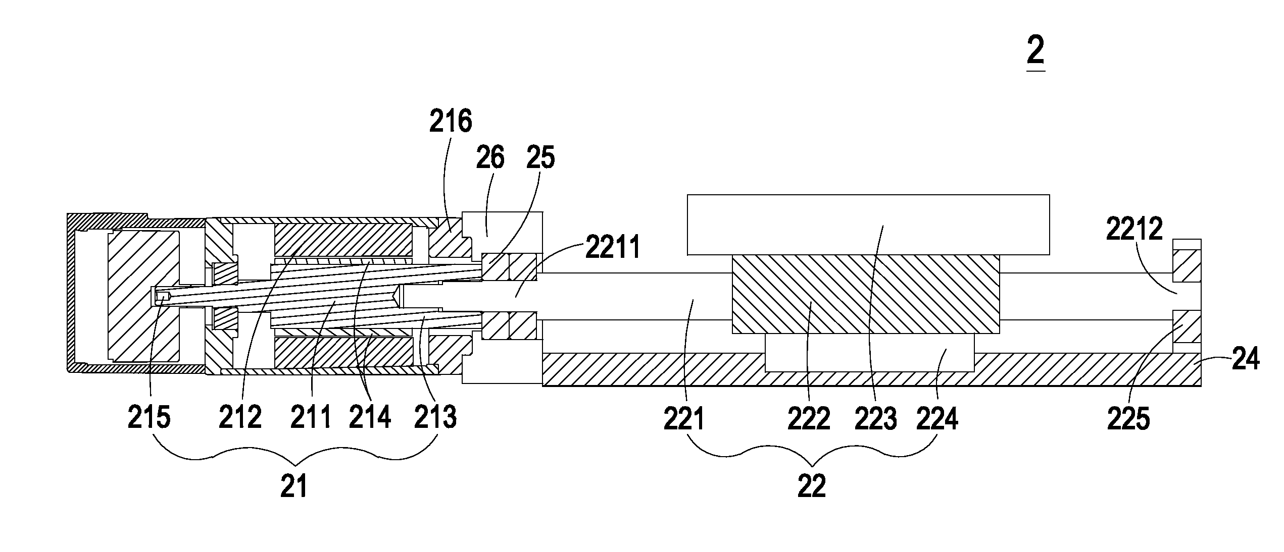
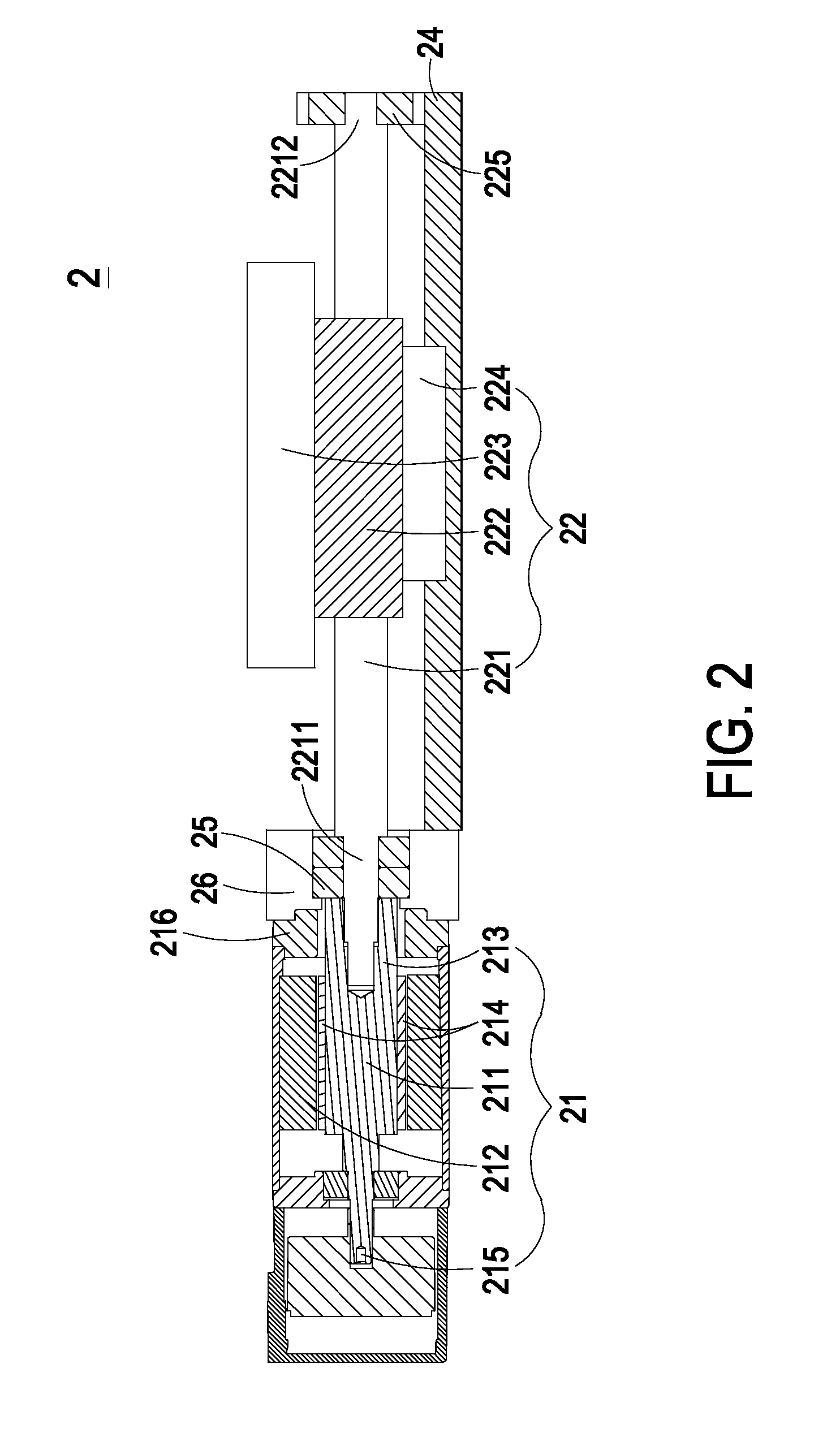
[0020]FIG. 2 is a schematic longitudinal cross-sectional view showing a motor driven linear actuator according to one preferred embodiment of the present invention; and FIG. 3 is an enlarged partial view illustrating the coupling structure among the motor shaft of the electric motor, the rolling bearing and the screw of the ballscrew device of FIG. 2. As shown in FIGS. 2 and 3, the motor driven linear actuator 2 includes an electric motor 21, a ballscrew device 22, a frame 24, and a rolling bearing 25. Preferably, the electric motor 21 is a servo motor, and the rolling bearing 25 is an angular ball bearing. In some embodiments, t...


PUM


Abstract

A motor driven linear actuator comprises an electric motor, a ballscrew device, and a rolling bearing. The electric motor includes a motor shaft having a first end portion. The first end portion includes an end surface and a receptacle having a first accommodation space. The ballscrew device includes a screw having a first end portion coaxially connected to the first end portion of the motor shaft. The first end portion of the screw includes a first section to be accommodated in the first accommodation space for fixing the screw with the motor shaft. The rolling bearing is disposed between the electric motor and the ballscrew device for supporting the first end portion of the screw. The end surface of the motor shaft contacts and abuts against the rolling bearing for limiting the movement of the rolling bearing between the electric motor and the ballscrew device.

Description

CROSS-REFERENCE TO RELATED APPLICATION[0001]This application claims the benefit of U.S. Provisional Application No. 61 / 866,759 filed on Aug. 16, 2013, and entitled “MOTOR DRIVEN LINEAR ACTUATOR AND ELECTRIC MOTOR THEREOF”, the entirety of which is hereby incorporated by reference.FIELD OF THE INVENTION[0002]The present invention relates to an actuator and an electric motor thereof, and more particularly to a motor driven linear actuator and an electric motor thereof.BACKGROUND OF THE INVENTION[0003]Motor driven linear actuators are well known in the art and used in a variety of applications, such as industrial machinery, precision machine tools, electronic machinery, transport machinery, and etc. The motor driven linear actuator conventionally converts the rotary motion of an electric motor to linear motion by using a ballscrew device.[0004]FIG. 1 is a schematic longitudinal cross-sectional view showing a conventional motor driven linear actuator. The conventional motor driven linea...

Claims


Application Information

Patent Timeline
Patent Type & Authority Applications(United States)
IPC IPC(8): F16H25/22
CPCF16H25/2204F16H25/20F16H2025/2075Y10T74/18576
Inventor TSAI, CHING-HSIUNGSU, CHUN-CHINCHUNG, CHI-WENCHU, EN-YI
Owner DELTA ELECTRONICS INC
Features
  • Generate Ideas
  • Intellectual Property
  • Life Sciences
  • Materials
  • Tech Scout
  • Unparalleled Data Quality
  • Higher Quality Content
  • 60% Fewer Hallucinations
Learn More