
Auto-adjusting membrane for respiratory interface device

a technology of respiratory interface and auto-adjusting membrane, which is applied in the direction of breathing mask, breathing protection, other medical devices, etc., can solve the problems of gas leakage from the mask at the gaps, unfavorable force, and considerable user discomfort and possible skin irritation and breakdown

Inactive Publication Date: 2015-02-19
KONINKLJIJKE PHILIPS NV
View PDF14 Cites 36 Cited by
  • Summary
  • Abstract
  • Description
  • Claims
  • Application Information

AI Technical Summary

Benefits of technology

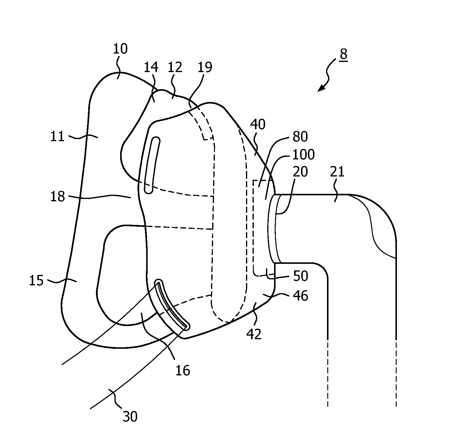
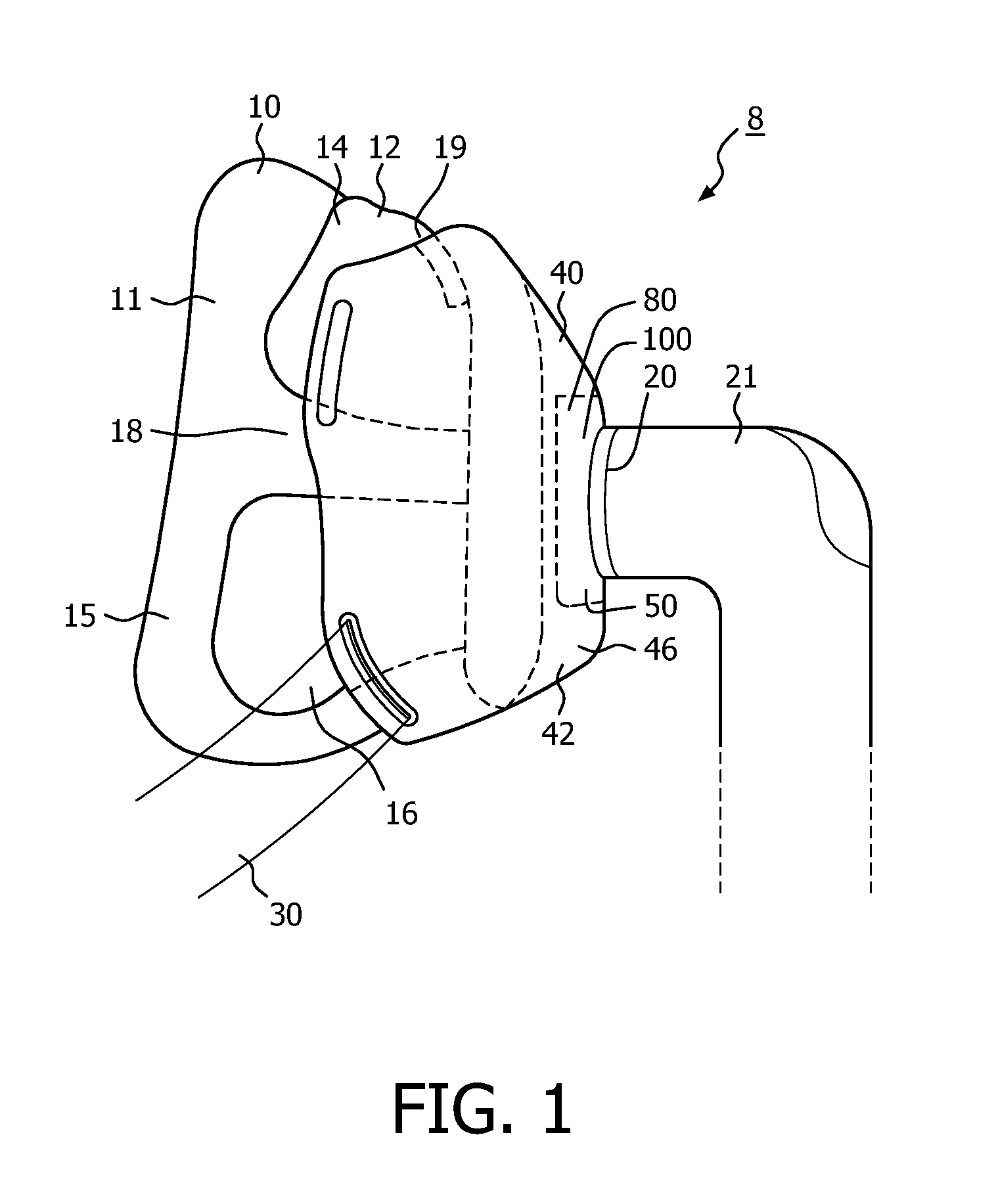
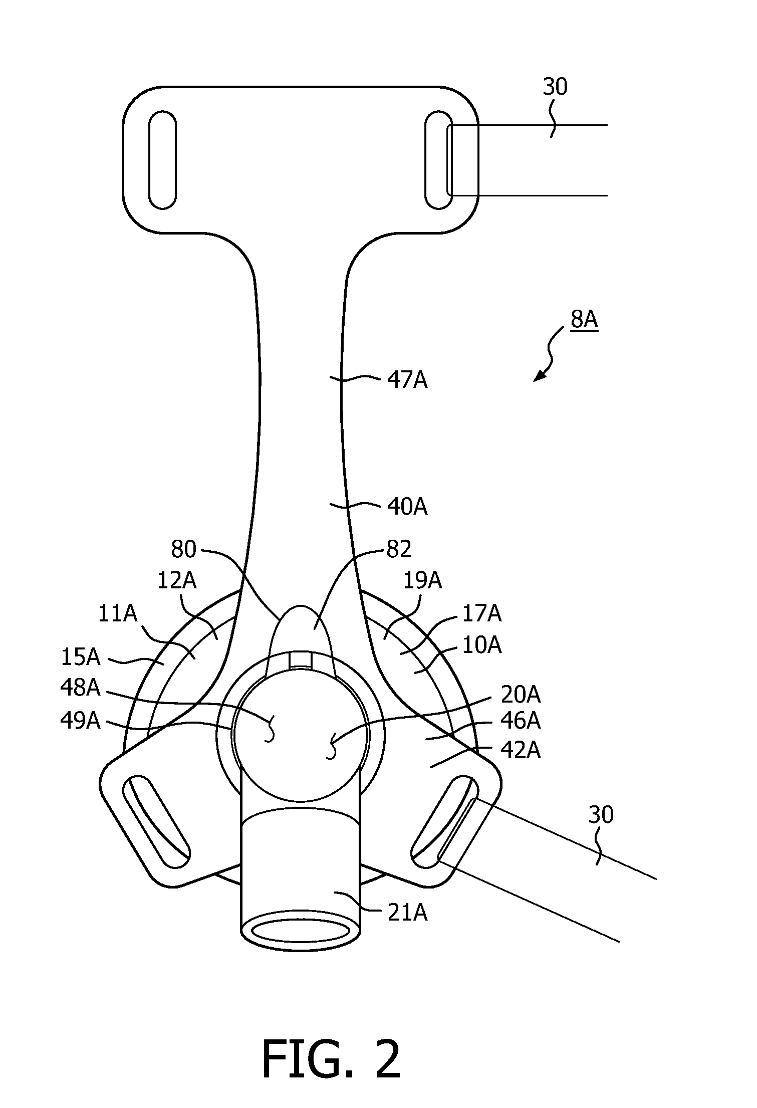
The invention is a respiratory interface device that has a soft coupling between the mask and the brace assembly. This soft coupling is achieved through a flexible membrane assembly that is positioned between the mask and the brace body. The flexible membrane assembly is designed to be resilient and deformable, but not overly deformable. When the straps are tightened, the brace body is biased towards the mask, resulting in a more complete seal between the patient's face and the cushion. The flexible membrane assembly automatically adapts to different facial geometries and properly orients the mask relative to the user's face. The technical effect of this invention is better seal, comfort, and a more secure and adjustable coupling between the mask and brace assembly.

Problems solved by technology

If the mask is not properly oriented or if the fit is not good, there will be gaps in the mask-to-face interface resulting in gas leaking from the mask at the gaps.
Such force is undesirable because it produces high pressure points elsewhere on the face of the user where the mask contour is forcibly deformed against the face to conform to the user's facial contours.
This will produce considerable user discomfort and possible skin irritation and breakdown anywhere the applied force exceeds the local perfusion pressure, which is the pressure that is sufficient to cut off surface blood flow.
This adjustment, however, places the straps closer to the user's eyes, which is generally considered to be uncomfortable.
Additional straps, however, are also generally considered to be uncomfortable.
That is, the mask will not be properly oriented in that the mask is, essentially, tilted upwardly.
This may create a gap along the lower edge of the mask sealing surface.
The user, however, may overcompensate thereby creating a gap along the upper edge of the mask sealing surface.
Such strap adjustments may continue and may result in a mask that is too tight or otherwise uncomfortable.

Method used


Image

  • Auto-adjusting membrane for respiratory interface device
  • Auto-adjusting membrane for respiratory interface device
  • Auto-adjusting membrane for respiratory interface device

Examples


Embodiment Construction

[0027]As used herein, the singular form of “a”, “an”, and “the” include plural references unless the context clearly dictates otherwise. As used herein, the statement that two or more parts or components are “coupled shall mean that the parts are joined or operate together either directly or indirectly, i.e., through one or more intermediate parts or components, so long as a link occurs. As used herein, “directly coupled” means that two elements are directly in contact with each other. As used herein, “fixedly coupled” or “fixed” means that two components are coupled so as to move as one while maintaining a constant orientation relative to each other. As used herein, a “contact coupling” means that contacting parts are biased toward each other. That is, parts that merely contact each other without any bias do not form a “contact coupling.”

[0028]As used herein, “rigid” means inflexible and non-compressible. As used herein, “stiff” means substantially inflexible and non-compressible b...


PUM


Abstract

A respiratory interface device is provided. The respiratory interface device includes a mask (10) having a faceplate (12) and a patient contacting cushion (15), the patient contacting cushion coupled to, and extending about, the faceplate, a brace assembly (40) having a brace body (42) with at least one mask coupling, the mask and the brace assembly coupled at the mask coupling, wherein the mask coupling. The mask soft coupling utilizes a flexible membrane assembly, the flexible membrane assembly being disposed between the mask and the brace body.

Description

CROSS-REFERENCE TO RELATED APPLICATIONS[0001]This patent application claims the priority benefit under 35 U.S.C. §119(e) of U.S. Provisional Application No. 61 / 636,206 filed on Apr. 20, 2012, the contents of which are herein incorporated by reference.BACKGROUND OF THE INVENTION[0002]1. Field of the Invention[0003]The present invention relates to respiratory interface devices for transporting a gas to and / or from an airway of a user which include, but not limited to, a mask having a flexible faceplate or patient contacting cushion, and in particular to a flexible respiratory interface device that is supported by a brace and having a flexible membrane assembly disposed between the mask and the brace body.[0004]2. Description of the Related Art[0005]A variety of respiratory masks are known which cover the areas surrounding the nose and / or mouth of a human user and that are designed to create an effective fit against the user's face. Typically, gases can be provided at a positive pressu...

Claims


Application Information

Patent Timeline
Patent Type & Authority Applications(United States)
IPC IPC(8): A61M16/06A61M16/08
CPCA61M16/065A61M16/0816A61M16/0622A61M16/06A61M16/0683A61M2205/0216A61M16/0605A61M16/0616A61M16/0633
Inventor MCCASLIN, JONATHAN PAUL
Owner KONINKLJIJKE PHILIPS NV
Learn More