
Firewall, pylon of aircraft, and aircraft

a technology of aircraft pylons and firewalls, applied in the field of firewalls, can solve the problems of increasing the time needed for maintenance, and achieve the effect of preventing flames from reaching the connecting parts

Active Publication Date: 2015-02-19
MITSUBISHI AIRCRAFT
View PDF6 Cites 22 Cited by
  • Summary
  • Abstract
  • Description
  • Claims
  • Application Information

AI Technical Summary

Benefits of technology

The firewall of this patent has a feature called a fire-protection chamber that prevents flames from reaching the connection between two objects, even if a fire breaks out inside the chamber. This feature is achieved by creating a barrier that can withstand fire and flames. The firewall can also have a passageway that allows air to flow in and out of the chamber, which further prevents fire from reaching the connection. Overall, this design prevents damage and minimizes the risk of fire outbreaks.

Problems solved by technology

However, fire-resistant sealant, in some cases, requires a longer time to be dried and hardened after the application thereof, which increases the time needed to perform maintenance.

Method used


Image

  • Firewall, pylon of aircraft, and aircraft
  • Firewall, pylon of aircraft, and aircraft
  • Firewall, pylon of aircraft, and aircraft

Examples


Embodiment Construction

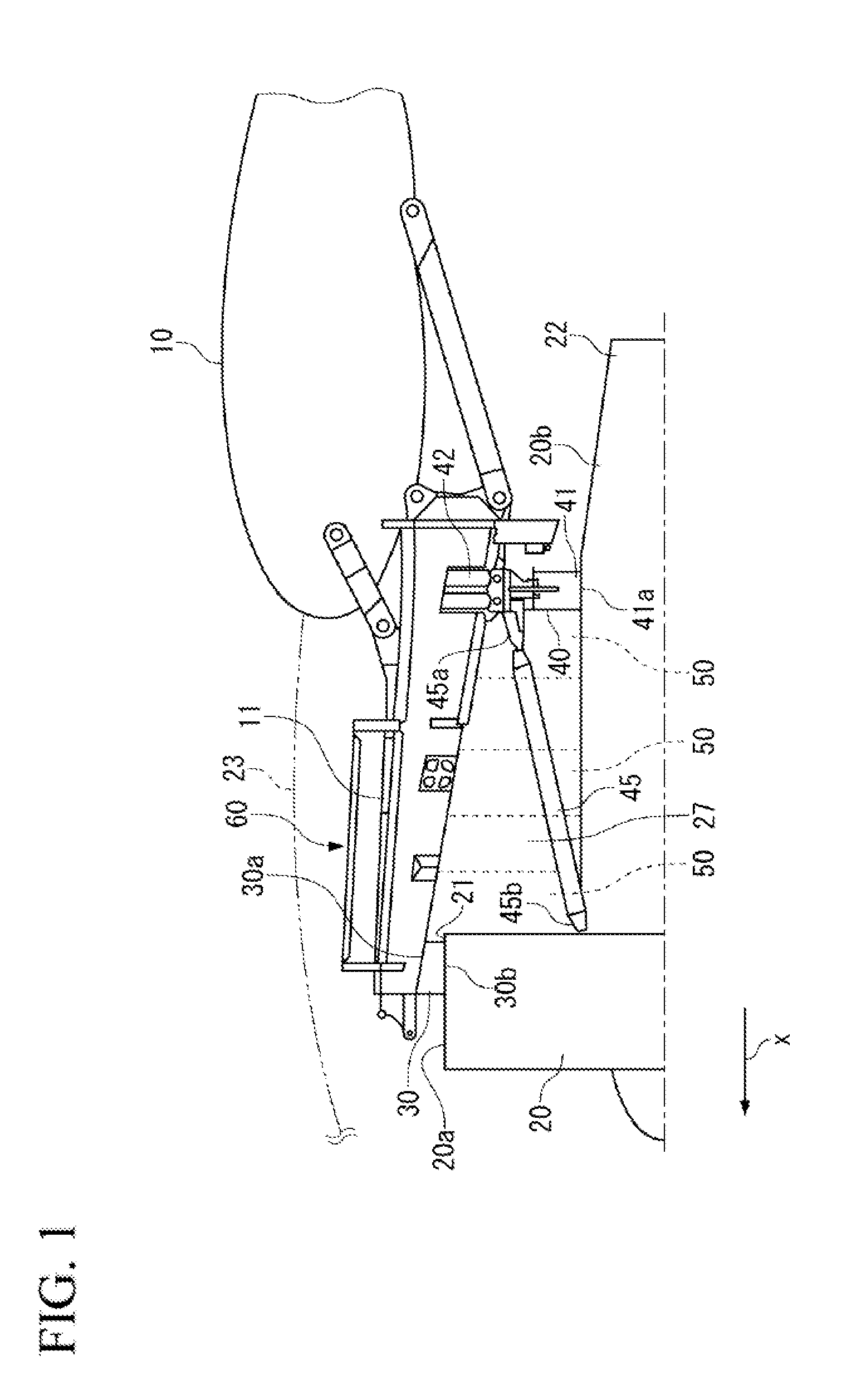
[0026]Hereinafter, a firewall according to the present invention will be described in accordance with an embodiment in which the firewall is mounted to a pylon 60.

[0027]As shown in FIG. 1, the pylon 60 of the present embodiment supports a turbofan type engine 20 and is mounted to a wing 10 of an aircraft. The pylon 60 is configured to include a pylon strut 11 and a nacelle 23.

[0028]The pylon strut 11 is provided at an undersurface of the wing 10 to extend toward a front (x) in a flying direction (See FIG. 1). The shape of the pylon strut 11 in a section orthogonal to a longitudinal direction is, for example, trapezoidal, and its sectional area gradually reduces toward the front side from the rear side.

[0029]The engine 20 includes a fan section 20a provided at the front (x) in the flying direction, and an engine core section 20b provided at the rear of the fan section 20a. The fan section 20a is provided with a fan incorporated inside a shroud 21 that is circular in section. The engi...


PUM


Abstract

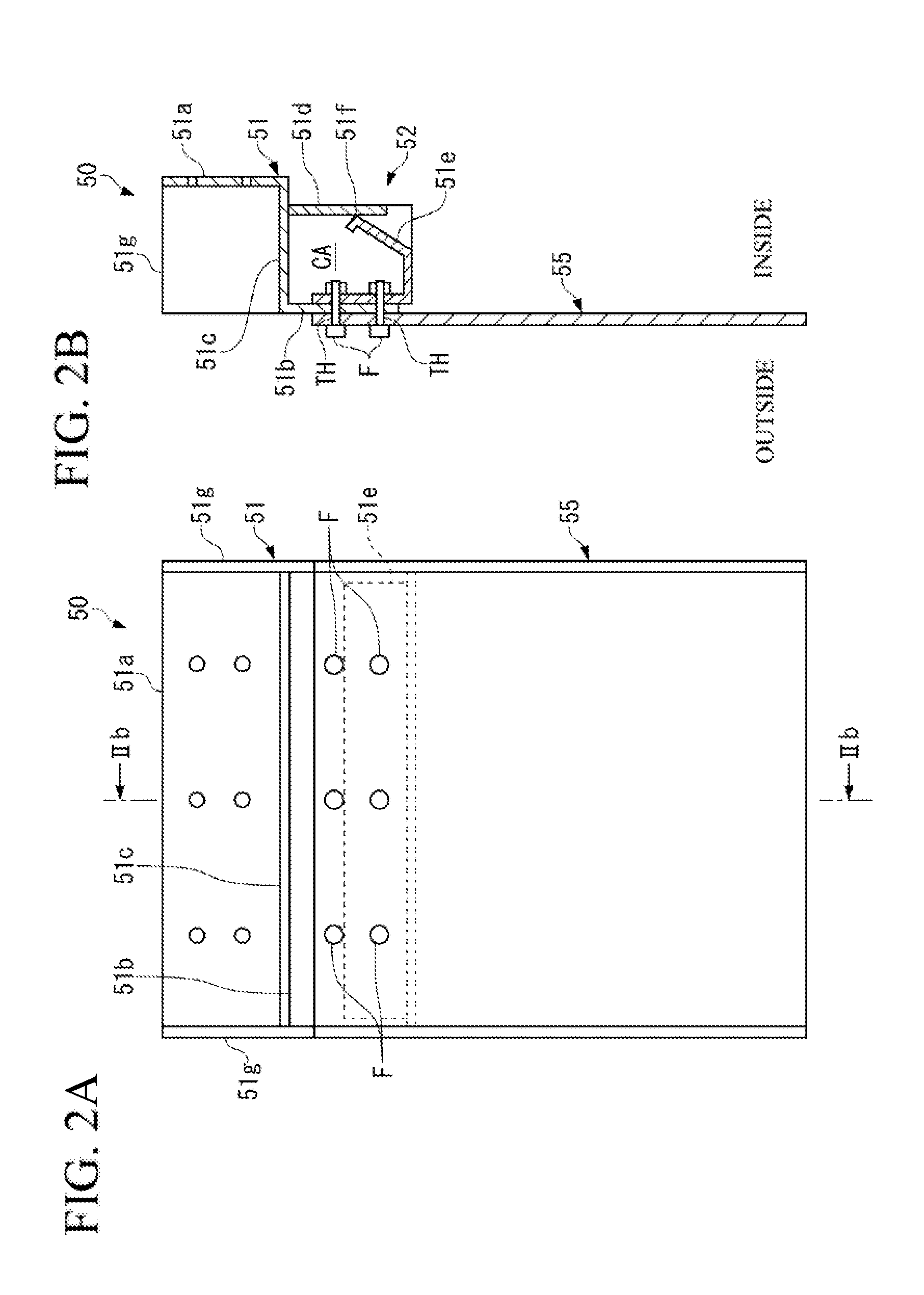
In order to provide a firewall that is capable of preventing flame passage through a through-hole without any sealant in a connecting part of a component in which a fastener through-hole is formed, a firewall 50 is provided which can prevent a flame from leaking out of the connecting part which connects a first member 51 to a second member 55, particularly through the fastener through-hole TH defined therein. In the firewall 50, the connecting part is a part of a fire-protection chamber 52. As sealing pieces 51d and 51e which also constitute a part of the fire-protection chamber 52 are in contact with each other, the flame is unable to enter into a closed space CA. Thus, the flame would not reach the connecting part, thereby preventing the flame from leaking out of the firewall 50 to the outside of a nacelle 23.

Description

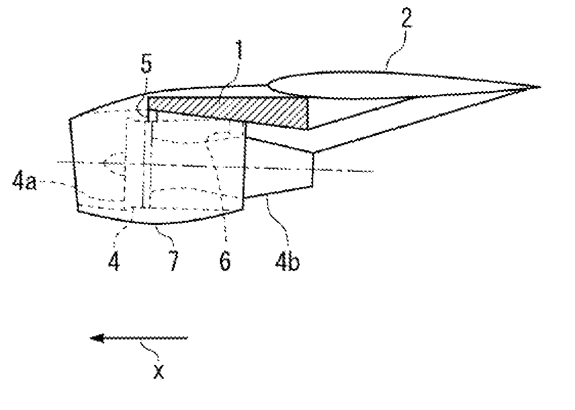
BACKGROUND OF THE INVENTION[0001]1. Field of the Invention[0002]The present invention relates to a firewall that is attached to an aircraft pylon for mounting an engine of an aircraft to a wing.[0003]2. Description of the Related Art[0004]A turbofan type engine of an aircraft is mounted to a wing via a structural member called a pylon strut (see, for example, Japanese Patent Laid-Open No. 2011-116186).[0005]As shown in FIG. 5, a pylon strut 1 is provided on an undersurface of a wing 2 so as to extend toward a front (x) in a flying direction. An engine 4 includes a fan section 4a at the front thereof which is mounted to an undersurface of the pylon strut 1 by a front engine mount 5, and a core section 4b at the rear thereof which is mounted to the undersurface of the pylon strut 1 by a rear engine mount 6. The engine 4 is covered by a cylindrical nacelle 7. The nacelle 7 has a structure capable of being opened and closed. Opening the nacelle towards right and left enables maintenance...

Claims


Application Information

Patent Timeline
Patent Type & Authority Applications(United States)
IPC IPC(8): F02C7/25A62C2/06B64D29/00B64D27/00B64D45/00
CPCF02C7/25B64D27/00B64D2045/009B64D29/00A62C2/06B64D45/00F02C7/20A62C3/08B64C7/00B64D27/402B64D27/40
Inventor TAKEUCHI, AKIRA
Owner MITSUBISHI AIRCRAFT
Learn More