Three-dimensional pointing using one camera and three aligned lights

a three-dimensional pointing and three-dimensional technology, applied in the field of humancomputer interaction systems, can solve the problems of difficult to achieve the use of conventional optical mouse, difficult to achieve the use of alternative pointing/input devices such as touchpads or trackballs, and the use of drawing programs without a computer mouse is difficult if not impossibl

Active Publication Date: 2015-02-19
AMCHAELVISUAL TECH LLC
View PDF3 Cites 14 Cited by
  • Summary
  • Abstract
  • Description
  • Claims
  • Application Information

AI Technical Summary

Benefits of technology

[0016]To solve the foregoing problems and address the identified need in the art, the present disclosure provides a human-computer interaction system supporting 2D and 3D pointing in “air mode.” In the following, for easy reference the term “air mode” refers to the operation of a pointing/input device in the air, i.e. 3D space, and the term “surface mode” refers to the operation of a pointing/input device on a surface such as a desk. The system uses ...

Problems solved by technology

If a suitable operating surface is not available and an alternative such as a touchpad or trackball is also not available, a conventional optical mouse cannot be used.
In turn, certain tasks often done with pointing/input devices such as a computer mouse are difficult to impossible to accomplish with alternative pointing/input devices such as touchpads or trackballs.
For example, use of drawing programs without a computer mouse can be difficult if not impossible.
Likewise, tasks such as two-dimensional (2D) or 3D sculpturing or drawing, “flying” in multi-dimensional space (for example, three-dimensional space defined by X, Y, and Z axes) such as during gaming, etc. would be difficult to accomplish using a conventional touchpad, trackball, etc.
Unfortunately, traditional television remote controls cannot conveniently provide such functionality.
H...

Method used


Image

  • Three-dimensional pointing using one camera and three aligned lights
  • Three-dimensional pointing using one camera and three aligned lights
  • Three-dimensional pointing using one camera and three aligned lights

Examples


Embodiment Construction

[0036]In the following detailed description of the illustrated embodiments, reference is made to the accompanying drawings that form a part hereof, and in which is shown by way of illustration, specific embodiments in which the invention may be practiced. These embodiments are described in sufficient detail to enable those skilled in the art to practice the invention. Also, it is to be understood that other embodiments may be utilized and that process, reagent, materials, software, and / or other changes may be made without departing from the scope of the present invention.

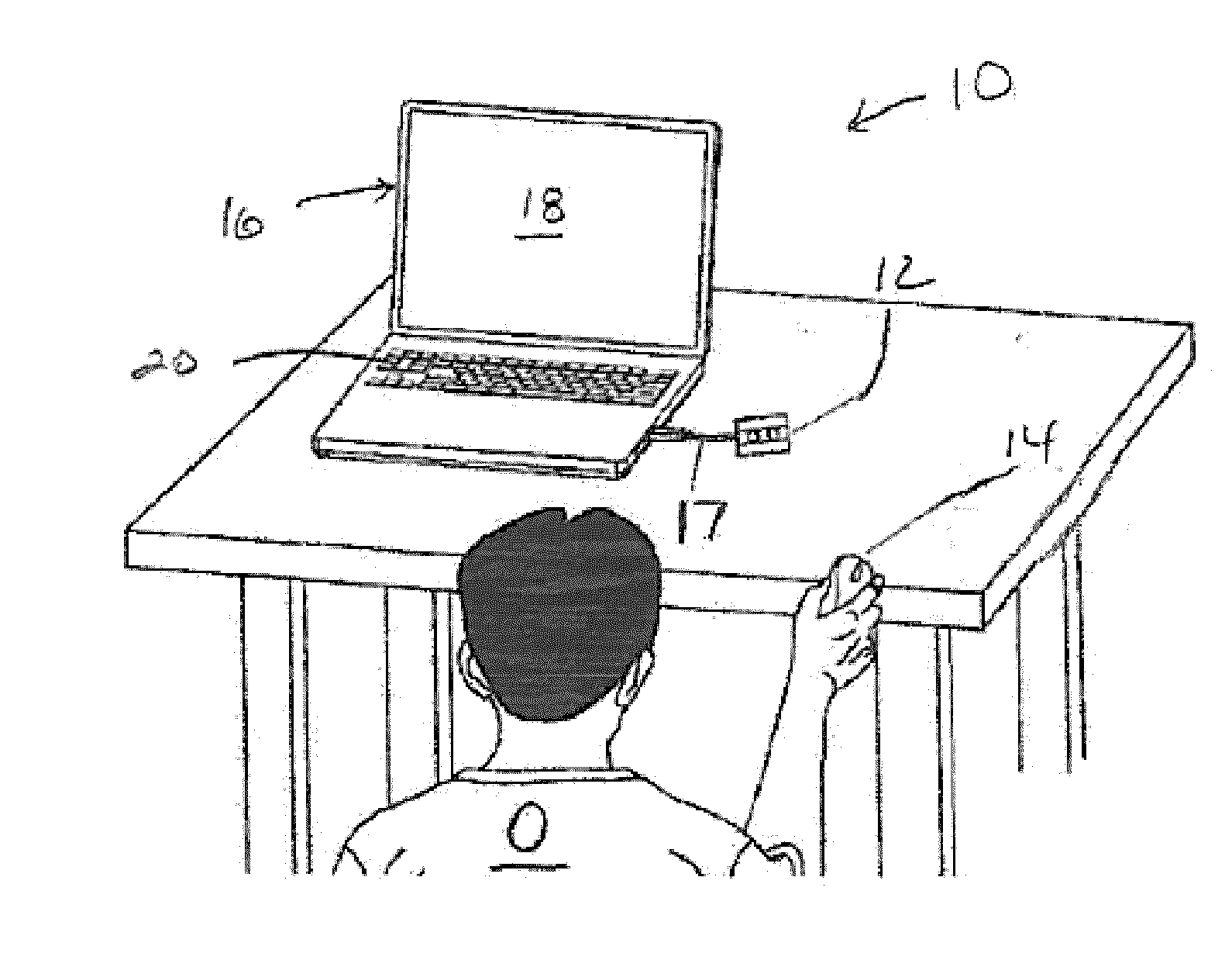
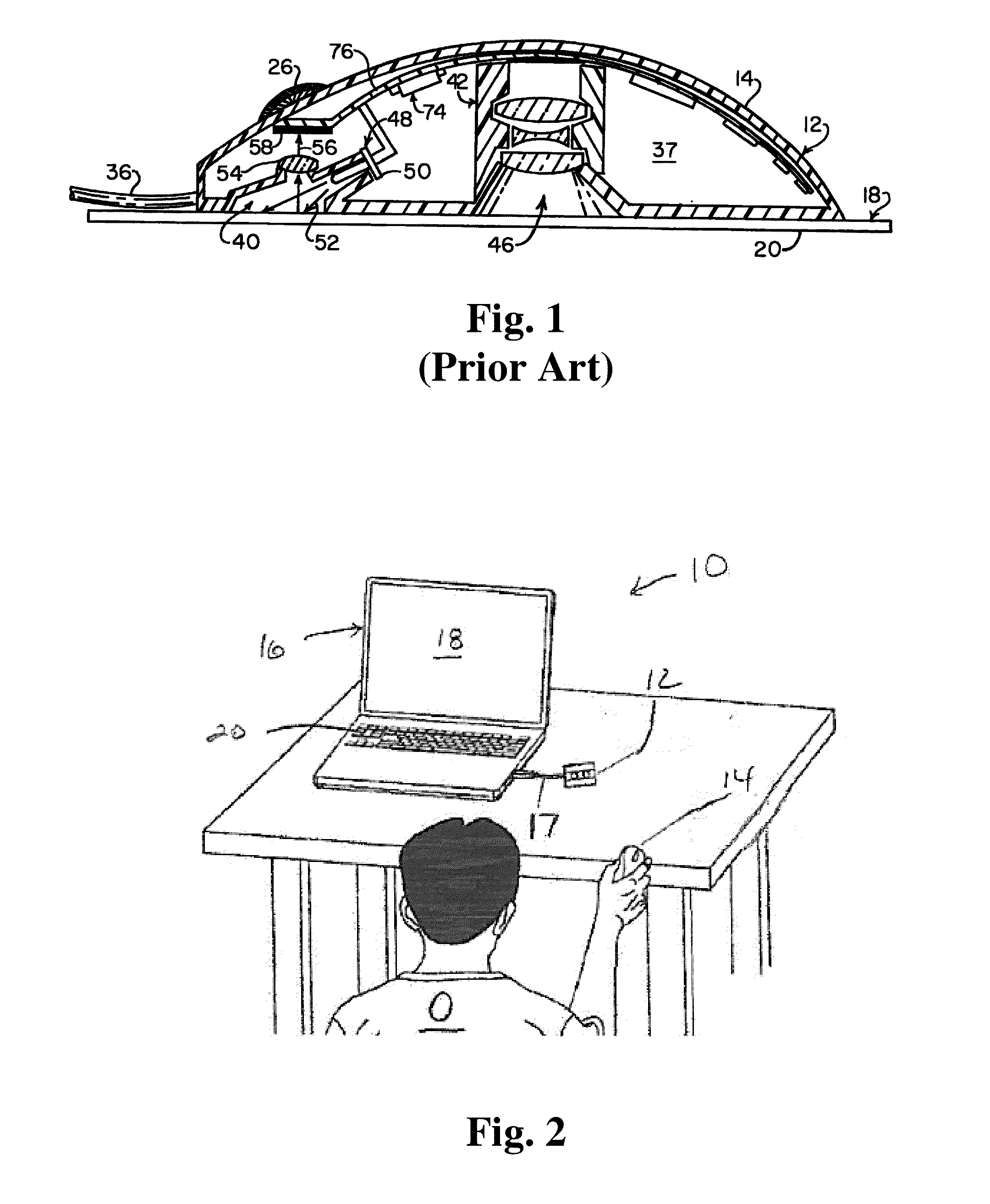
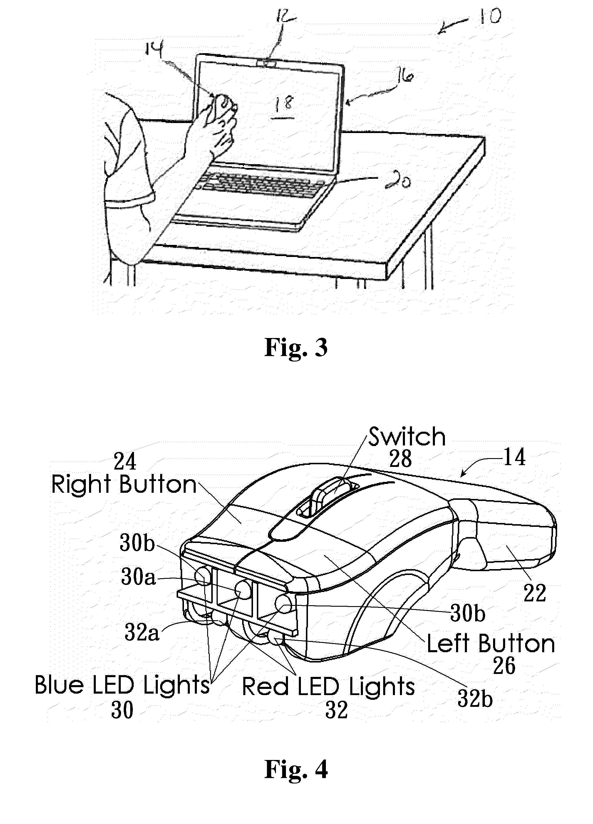
[0037]The present disclosure relates to a human-computer interaction system 10 that allows 2D and 3D pointing operations in air mode, i.e. without any requirement for translating a pointing device over a surface to measure a distance displacement thereof. The system 10 comprises a specialized pointing / input device 14, an imaging device 12, and at least one light tracking computer program. The imaging device 12 may b...


PUM


Abstract

Methods and systems for surface-free pointing and/or command input include a computing device operably linked to an imaging device. The imaging device can be any suitable video recording device including a conventional webcam. At least one pointing/input device is provided including first and second sets of visible point light sources, wherein the first and second sets emit differently colored light. The imaging device captures one or more sequential image frames each including a view of a scene including the first and second sets of visible point light sources. One or more software programs calculate a position and/or a motion and/or an orientation of the pointing/input device in the captured image frames by identifying colored areas corresponding to the first set of aligned visible point light sources. Certain activation patterns of individual point light sources are mapped to particular pointing and/or input commands.

Description

[0001]This utility patent application claims the benefit of priority in U.S. Provisional Patent Application Ser. No. 61 / 865,630 filed on Aug. 14, 2013, the entirety of the disclosure of which is incorporated herein by reference.TECHNICAL FIELD[0002]The present disclosure relates to human-computer interaction systems. More specifically, this disclosure pertains to methods and systems for use of a conventional video recorder such as a webcam for two-dimensional (2D) and three-dimensional (3D) pointing and command inputs in a computing system relying on passive light detection for both 2D and 3D modes. Embodiments of a pointing / input device for use in the methods and systems are disclosed.BACKGROUND OF THE INVENTION[0003]The operation of a conventional mechanical or optical pointing or input device such as a mechanical or optical computer mouse is well known in the art. By use of these devices, the user can select files, programs, or actions from lists, groups of icons, etc., and can “...

Claims


Application Information

Patent Timeline
IPC IPC(8): G06F3/0354
CPCG06F3/03543G06F3/0325
Inventor CHENG, KAI MICHAELTSAI, YUSHIUANLU, HSIEN-CHENG
Owner AMCHAELVISUAL TECH LLC
Why Eureka
Try Eureka