Simplified nasal dilator

Inactive Publication Date: 2015-02-19
INFINITE FINANCIAL SOLUTIONS
View PDF5 Cites 44 Cited by
  • Summary
  • Abstract
  • Description
  • Claims
  • Application Information

AI Technical Summary

Benefits of technology

[0023]The unique advantage of the present invention will become apparent to one skilled in the art upon reading the following specifications and by reference to the following drawings:
[0024]FIG. 1 is a side view of the di

Problems solved by technology

Most medical grade adhesives are designed to be used in applications where there are shear loads on the adhesive and unless the adhesives have a very aggressive adherence characteristics and high internal strength, they will not have the necessary adhesive strength to overcome the restoring forces of the resil

Method used


Image

  • Simplified nasal dilator
  • Simplified nasal dilator
  • Simplified nasal dilator

Examples


Embodiment Construction

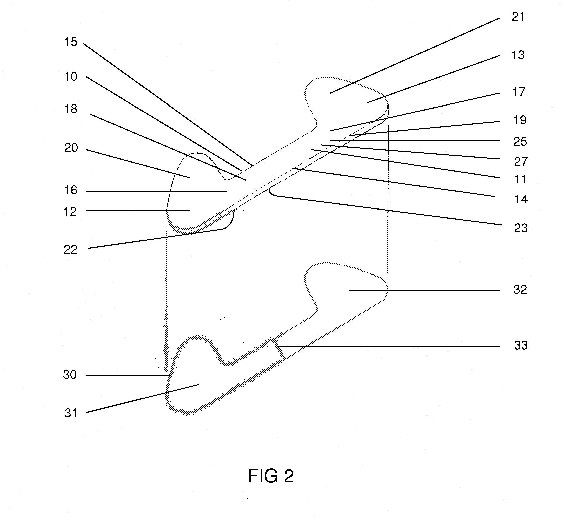
[0027]The specific improvements provided by this invention over past nasal dilators described in the prior art are best seen in the attached drawings.

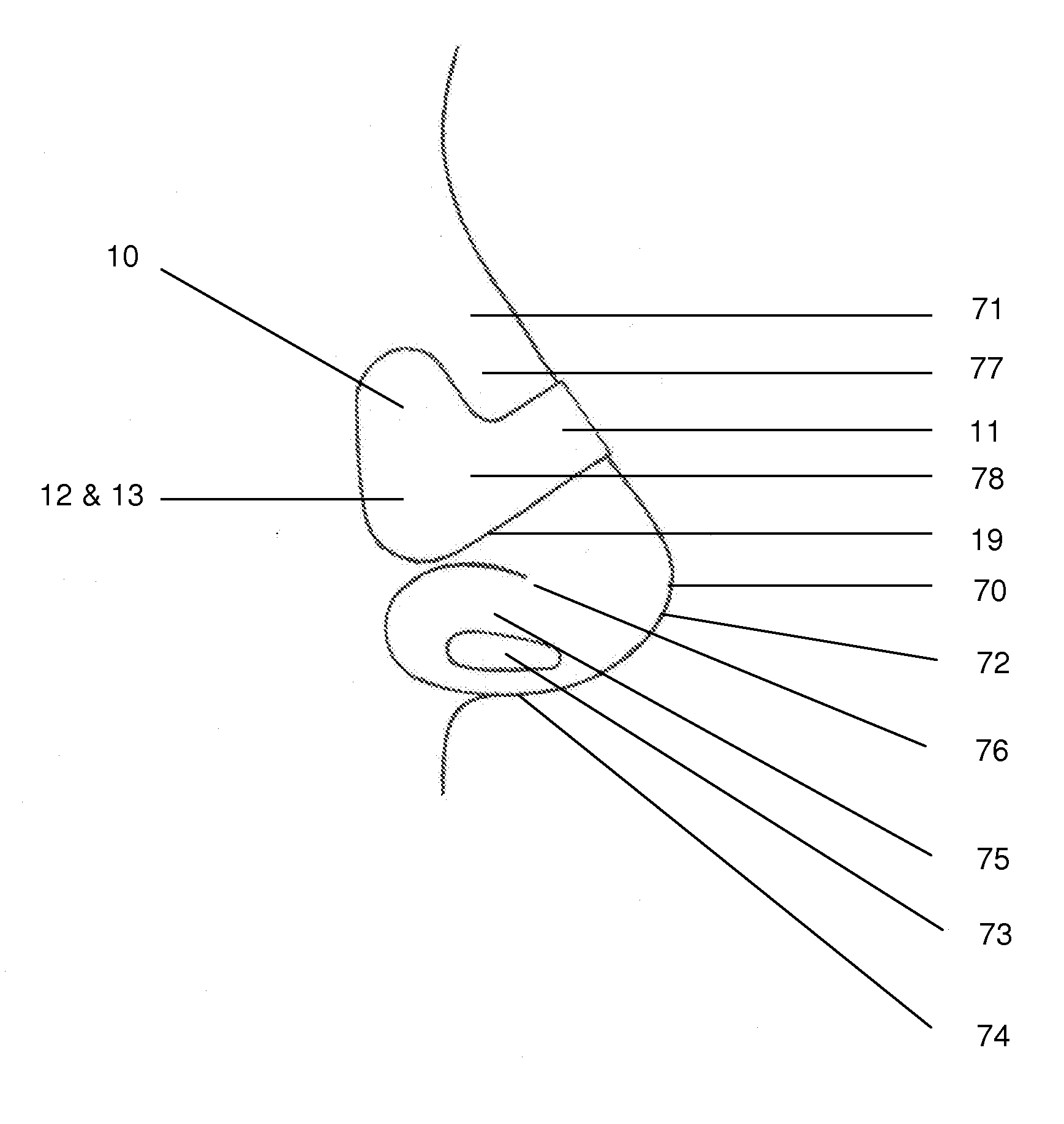
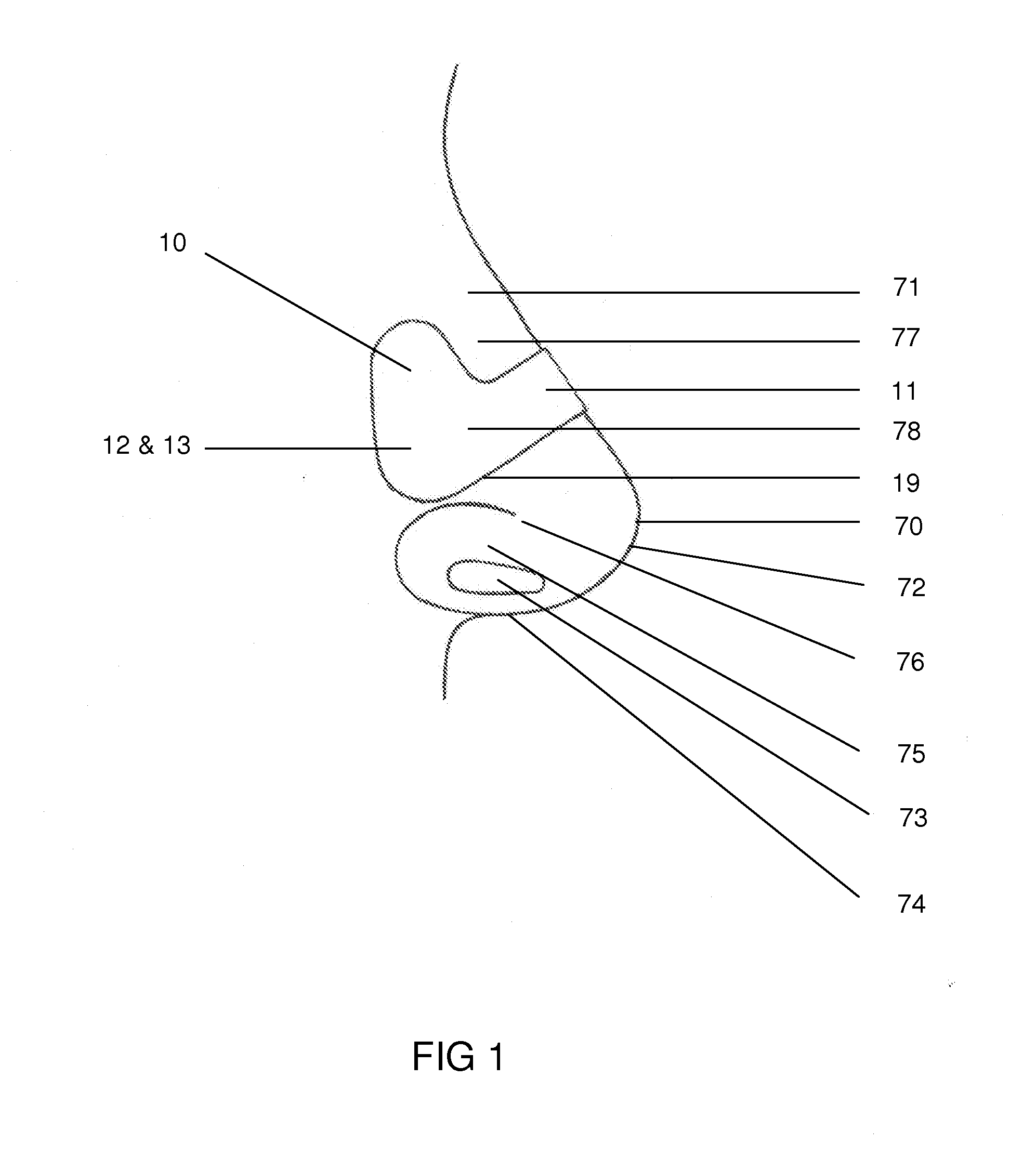
[0028]Referring to FIG. 1 the new dilator 10 is mounted on the nose 70 of the user. The nasal dilator 10 has an intermediate section 11 that is bent over the bridge 71 of the nose 70 and each end 12 and 13 of the nasal dilator 10 is positioned over the lateral surface 77 of the nose 70.

[0029]The structure of the nose 70 is important to demonstrate the unique advantages of the nasal dilator 10 in this invention. Starting at the tip of the nose 70 we have the apex 72 and at the bottom of the nose 70 and between the two nostrils 73 we have the septum 74. Above and on the outside surface of each nostril 73, there is a surface known as the ala (wing) 75. The boundary of the ala 75 and the lateral surface 77 is the alar furrow 76 which is a heavily contoured demarcation. The lateral surface 77 is on each side of the nose 70 and is a flat sur...


PUM


Abstract

A nasal dilator capable of introducing separating forces in the nasal outer wall tissue, has a resilient member, and a pair of spaced-apart end surfaces which can be forced toward one another from an initial flat position of the dilator to thereby substantially reduce the direct spacing therebetween by an external spacing reducing force. This results in restoring forces in the dilator tending to return it to the original direct spacing between the end surfaces. The resilient member, which is asymmetrical with respect to a centerline of the dilator that is parallel to the long axis of the dilator, has an extended surface at each end surface of the dilator which increases the adhesive surface area. The extended surface is located at each end surface of the resilient member on the side opposite the nose ala (wings) and above the alar furrow. An adhesive on the bottom surface of the resilient member adhesively engages exposed surfaces of the nasal outer wall tissues known as the lateral surface sufficiently to keep the dilator attached to the lateral wall while subjecting them to the restoring forces.

Description

BACKGROUND OF THE INVENTION[0001]This invention relates to the structure of nasal dilators which reduces the cost of manufacturing and improves the performance of the dilator. Current nasal dilator designs employ one of more resilient bands which are integrated into a nasal dilator structure with flexible material that defines each end of the dilator and the intermediate section therebetween. The nasal dilator structure has sufficient length, so that the resilient band can be bent over the bridge of the nose, and each end of the band becomes adhesively attached to the soft tissue on the external wall of the nasal passage.[0002]Bending the resilient band from its initial planar state to its deformed state with its ends in contact with the lateral walls of the nasal passages and the intermediate section of the band overlying the bridge of the nose results in forces tending to pull out on the lateral wall tissues which stabilize the walls of the nasal passages during breathing.[0003]Th...

Claims


Application Information

Patent Timeline
IPC IPC(8): A61F5/08A61M29/00
CPCA61M29/00A61F5/08
Inventor LOCKWOOD, JR., HANFORD N.
Owner INFINITE FINANCIAL SOLUTIONS
Why Eureka
Try Eureka