Storage system and storage system control method

a storage system and control method technology, applied in the direction of fault response, redundant data error correction, instruments, etc., can solve the problems of deteriorating performance of the storage system and increasing the amount of data transfer between nodes, so as to improve the performance of data access of the storage system and reduce the amount of data transfer between storage apparatuses

Inactive Publication Date: 2015-02-19
HITACHI LTD
View PDF5 Cites 9 Cited by
  • Summary
  • Abstract
  • Description
  • Claims
  • Application Information

AI Technical Summary

Benefits of technology

[0015]According to the aspect of the present invention, the data transfer between the storage apparatuses is reduced, so that performance of data access of the storage system can be improved.

Problems solved by technology

Recently, a data transfer amount between nodes is increased according to an increase in the number of nodes, and performance of the storage system is deteriorated because of a lack of a band of a network which couples the nodes.

Method used


Image

  • Storage system and storage system control method
  • Storage system and storage system control method
  • Storage system and storage system control method

Examples


first embodiment

[0053]In the embodiment, a case where a plurality of host computers do not share a virtual volume will be described.

[0054]Hereinafter, a configuration of a computer system according to the embodiment of the present invention will be described.

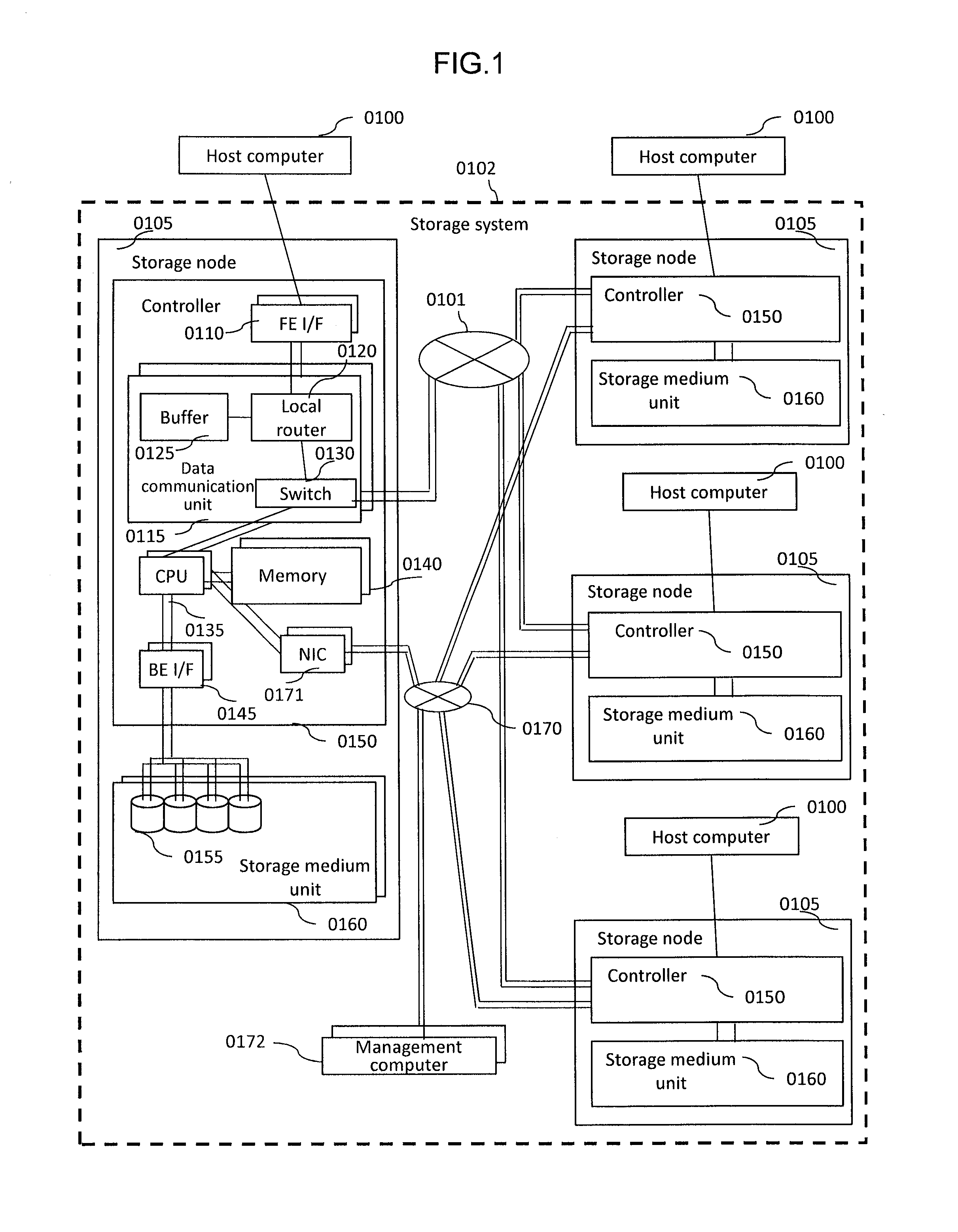
[0055]FIG. 1 illustrates a configuration of a computer system according to the embodiment of the present invention.

[0056]The computer system is configured to include a plurality of host computers 0100 and a storage system 0102. The storage system 0102 is configured to include a plurality of storage nodes 0105 and a management computer 0172. The plurality of storage nodes 0105 are coupled to the plurality of host computers 0100, respectively. In addition, the plurality of host computers 0100 may be coupled to one storage node 0105. The storage node 0105 is a storage apparatus and is coupled through a network 0101 (communication line) to other storage nodes 0105. The host computer 0100 transmits a write command (write request) for writing data in...

second embodiment

[0194]In the embodiment, a case where a plurality of the host computers shares a virtual volume will be described. Hereinafter, the description will be mainly made on the difference from the first embodiment.

[0195]FIG. 30 schematically illustrates sharing of a virtual volume.

[0196]The host computers 3205 and 3210 share a virtual volume 3215 provided by the storage system 0102. Namely, there is a case where the host computers 3205 and 3210 perform data access on the same virtual volume 3215. Each of the host computers 3205 and 3210 corresponds to the host computer 0100 of the first embodiment. Three or more host computers may be used. Two or more virtual volumes may be used.

[0197]The storage node 0105 in the storage system 0102 receives a write command from any one of the host computers 3205 and 3210 to the virtual storage area in the virtual volume 3215 and the drive area is not allocated to the virtual storage area. In this case, the storage node 0105 receiving the write command ex...


PUM


Abstract

Data transfer between storage apparatuses is reduced, and performance of data access of a storage system is improved. In a case where a processor of a first storage apparatus receives a write request from a host computer as a request for data access to a virtual volume and a cache memory of any of the storage apparatuses is not allocated to a virtual storage area in the virtual volume designated by the data access request, the processor of the first storage apparatus selects a second storage apparatus and a third storage apparatus among candidates satisfying a predetermined state condition among the storage apparatuses based on connection information indicating connection between the storage apparatuses through a communication line.

Description

TECHNICAL FIELD[0001]The present invention relates to a technique using a plurality of storage apparatuses.BACKGROUND ART[0002]In a storage system having a cluster configuration where a plurality of storage nodes are collected, the storage nodes are driven in parallel so that high performance of data access can be implemented due to parallel access and high availability can be implemented due to data redundancy. Hereinafter, in description and drawings, the storage node may be referred to as a node.[0003]Recently, a data transfer amount between nodes is increased according to an increase in the number of nodes, and performance of the storage system is deteriorated because of a lack of a band of a network which couples the nodes. Methods of solving the problem are known as follows.[0004]In a first method, a local cache is used (for example, PTL 1). In this method, in a cluster configuration where a plurality of storage apparatuses (nodes) are coupled through a network, when a data wr...

Claims


Application Information

Patent Timeline
Patent Type & Authority Applications(United States)
IPC IPC(8): G06F17/30G06F11/10
CPCG06F17/302G06F17/30091G06F17/30327G06F11/1076G06F17/30132G06F3/0605G06F3/0611G06F3/0635G06F3/0665G06F3/0689G06F2206/1008G06F16/13G06F16/172G06F16/1827G06F16/2246
Inventor AKAIKE, HIROTOSHIFUJIMOTO, KAZUHISATATARA, KOHEITANAKA, KATSUYAMIZUNO, MAKIO
Owner HITACHI LTD
Why Eureka
Try Eureka