
Method for evaluating output signals of a rotational rate sensor unit and rotational rate sensor unit

a technology of rotational rate sensor and output signal, which is applied in the direction of acceleration measurement using interia forces, navigation instruments, instruments, etc., can solve the problems of reducing the battery running time comparatively high power consumption, and the main processor of the portable device, so as to achieve substantially reduced power consumption, data transfer, and energy consumption. , the effect of reducing the battery running tim

Active Publication Date: 2014-10-09
ROBERT BOSCH GMBH
View PDF8 Cites 0 Cited by
  • Summary
  • Abstract
  • Description
  • Claims
  • Application Information

AI Technical Summary

Benefits of technology

This patent describes a sensor unit that can measure the rotation of an object using a special sensor. The sensor unit includes an evaluation circuit that can calculate the orientation of the object based on the measured movement. The evaluation circuit stores the changes in orientation in a register, which is connected to an external data processing unit. This allows for easy processing of the orientation changes without losing any valuable information. The sensor unit can be designed using a quaternion system, which makes it easy to represent rotations in three-dimensional space. By monitoring the length of the changes in orientation, the precision of the sensor can be improved. The sensor unit can be power-saving and can be implemented as an ASIC chip, making it ideal for portable devices. The technical effects of this patent include improved accuracy and efficiency in measuring rotational movements and reduced power consumption.

Problems solved by technology

A disadvantage is that, due to the high sampling rates, the main processor of the portable device has to be active relatively frequently in order to read out and further process the output signals of the rotational rate sensors.
This results in a comparatively high power consumption.
In particular in portable devices, due to limited battery capacities, this results in reduction of the battery running time of the portable device.
In this way, the maximum occurrence error can be limited.
This results in an errored calculation of the new change of orientation value in the third method step.
Due to a preferably only approximate calculation of the intermediate value, the danger that the change of orientation value has errors increases with each loop of the first, second, third, and fourth method steps.
In addition, it is possible that an interrupt is sent to the external data processing unit by the rotational rate sensor unit.

Method used


Image

  • Method for evaluating output signals of a rotational rate sensor unit and rotational rate sensor unit
  • Method for evaluating output signals of a rotational rate sensor unit and rotational rate sensor unit
  • Method for evaluating output signals of a rotational rate sensor unit and rotational rate sensor unit

Examples


Embodiment Construction

[0024]In the various Figures, identical parts are provided with identical reference characters, and are therefore in general only named or mentioned once.

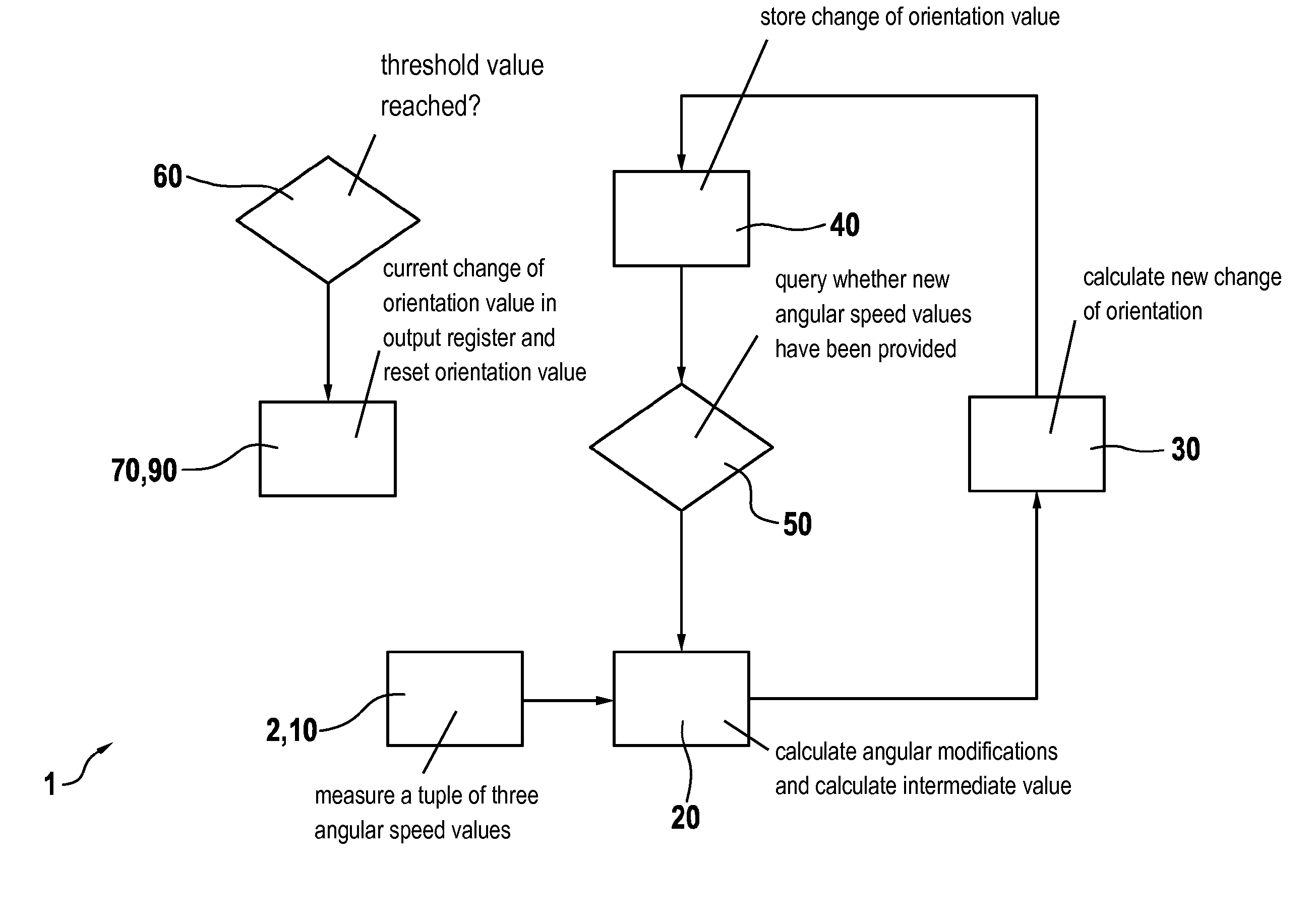
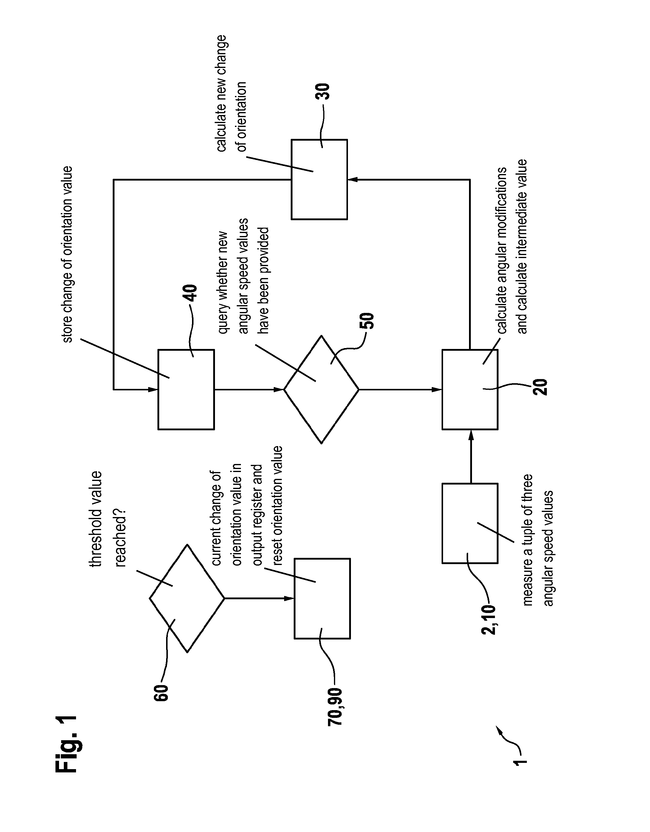
[0025]FIG. 1 shows a schematic view of a method for evaluating output signals of a rotational rate sensor unit 1 according to a first specific embodiment of the present invention. Rotational rate sensor unit 1 has a rotational rate sensor that measures rotational rates or angular speeds ωx, ωy, ωz about an X-axis, a Y-axis, and a Z-axis, the X, Y, and Z axes being independent of one another.

[0026]In a first method step 10, a tuple of three angular speed values ωx, ωx, and ωx is measured by the rotational rate sensor and provided. In a second method step 20, from the three angular speed values ωx, ωx, and ωx, and using sampling time T (which corresponds to 1 / data rate), respective angular modifications ωx·T, ωy·T and ωz·T are calculated. As a function of angular modification ωx·T, ωy·T, ωz·T, an intermediate value q· is then calcula...


PUM


Abstract

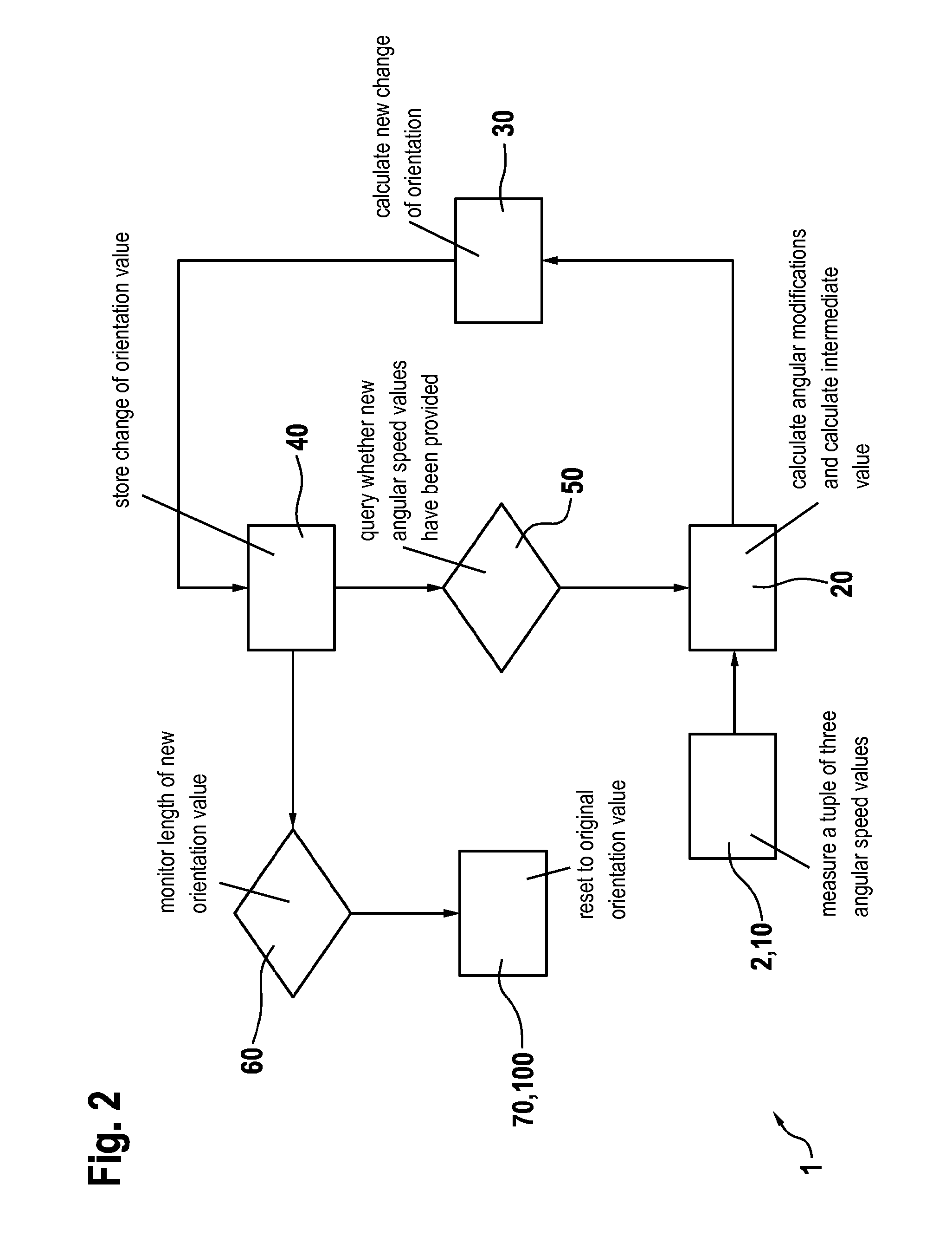
A method for evaluating output signals of a rotational rate sensor unit, including providing an n-tuple of angular speed values measured by at least one rotational rate sensor of the rotational rate sensor unit, in a first step; determining an intermediate value as a function of the n-tuple of angular speed values, in a second step; calculating a new change of orientation value as a function of the intermediate value and an earlier change of orientation value stored in a register of the rotational rate sensor unit, in a third step; and storing the new change of orientation value in the register, in a fourth step, repeating the first, second, third, and fourth step until, the new change of orientation value is read out by an external data processing unit connected to the rotational rate sensor unit, and / or, an exceeding of a threshold value is detected.

Description

FIELD[0001]The present invention is based on a method for evaluating output signals of a rotational rate sensor system, and on a rotational rate sensor system.BACKGROUND INFORMATION[0002]Rotational rate sensor systems are generally available. German Patent Application No. DE 101 108 196 A1 describes a rotational rate sensor having Coriolis elements for measuring an angular speed, a first and second Coriolis element being connected to one another via a spring and being excited to oscillations parallel to a first axis, a first and a second detection device detecting a deflection of the first and second Coriolis element based on a Coriolis force acting on the Coriolis elements, so that the difference between a first detection signal of the first detection device and a second detection signal of the second detection device is a function of the Coriolis force and is therefore also a function of the momentary angular speed.[0003]German Patent Application No. DE 10 2007 060 942 A1 describe...

Claims


Application Information

Patent Timeline
Patent Type & Authority Applications(United States)
IPC IPC(8): G01C19/5776
CPCG01C21/16G01C19/5776G01C21/188G01C21/18G01P7/00G01P3/44
Inventor CLAUS, THOMASBARTHOLOMEYCZIK, JULIAN
Owner ROBERT BOSCH GMBH
Learn More