
Method for replacing sloped cables, and temporary hanger for replacing sloped cables

Active Publication Date: 2015-02-26
IHI INFRASTRUCTURE SYST CO LTD
View PDF3 Cites 9 Cited by
  • Summary
  • Abstract
  • Description
  • Claims
  • Application Information

AI Technical Summary

Benefits of technology

The present invention simplifies the process of installing a stay cable by eliminating the need for a second stay cable to be hung in tension. This reduces the complexity of the operation and simplifies the number of facilities required for pulling the stay cable.

Problems solved by technology

However, another stay cable hung in tension above the target stay cable makes it very difficult for the crane to remove and hang the stay cable.
Additionally, in the method in FIG. 16B for hanging the stay cable, the stay cable has a large sag, which makes the amount of pulling of the stay cable large.
This increases the number of facilities for pulling the stay cable, and the pulling operation of the stay cable increases in complexity.

Method used


Image

  • Method for replacing sloped cables, and temporary hanger for replacing sloped cables
  • Method for replacing sloped cables, and temporary hanger for replacing sloped cables
  • Method for replacing sloped cables, and temporary hanger for replacing sloped cables

Examples


Embodiment Construction

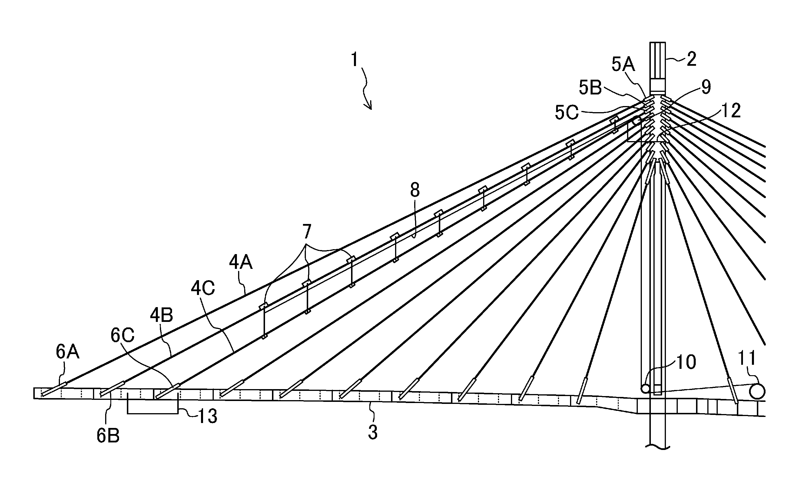
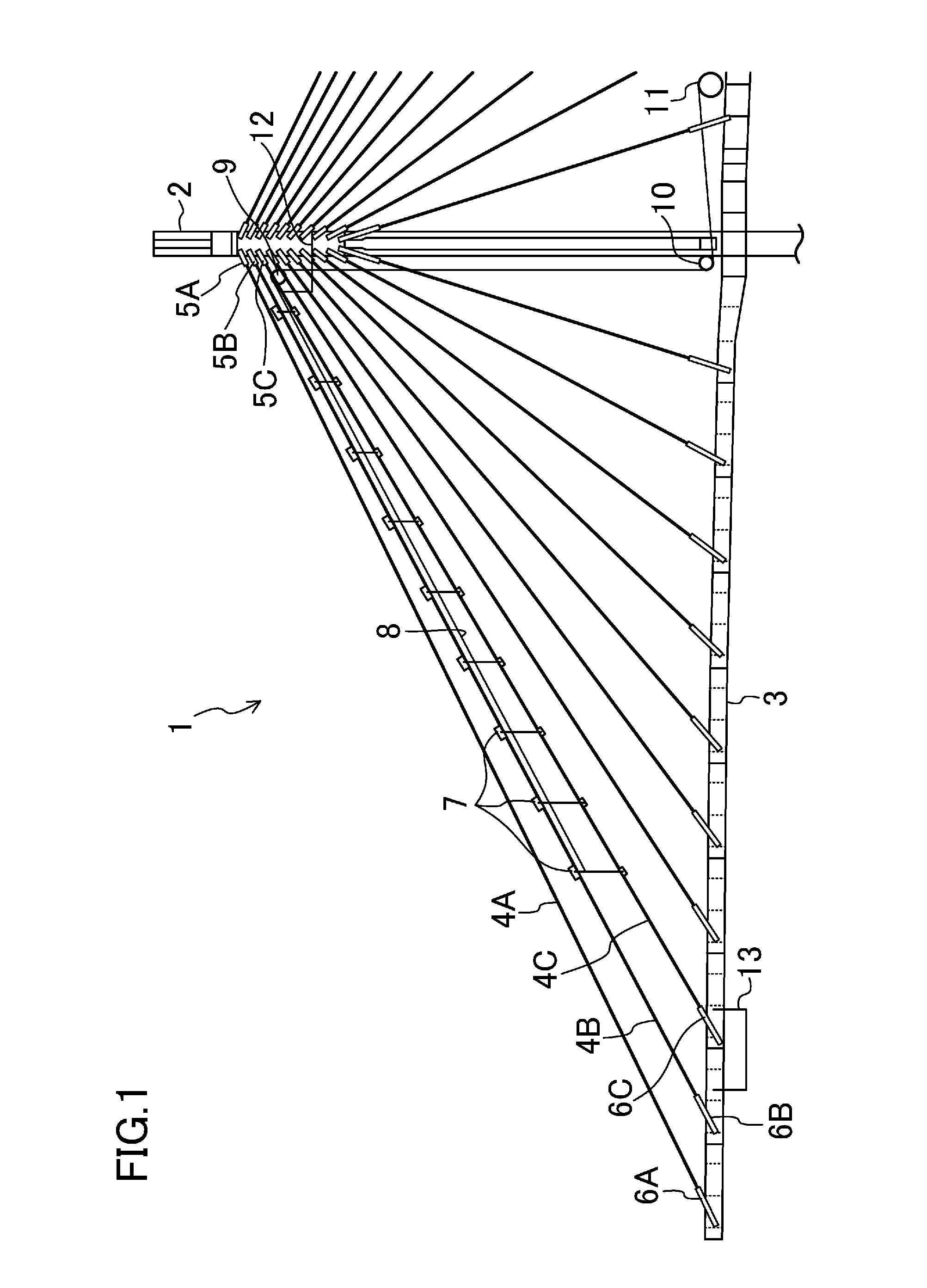
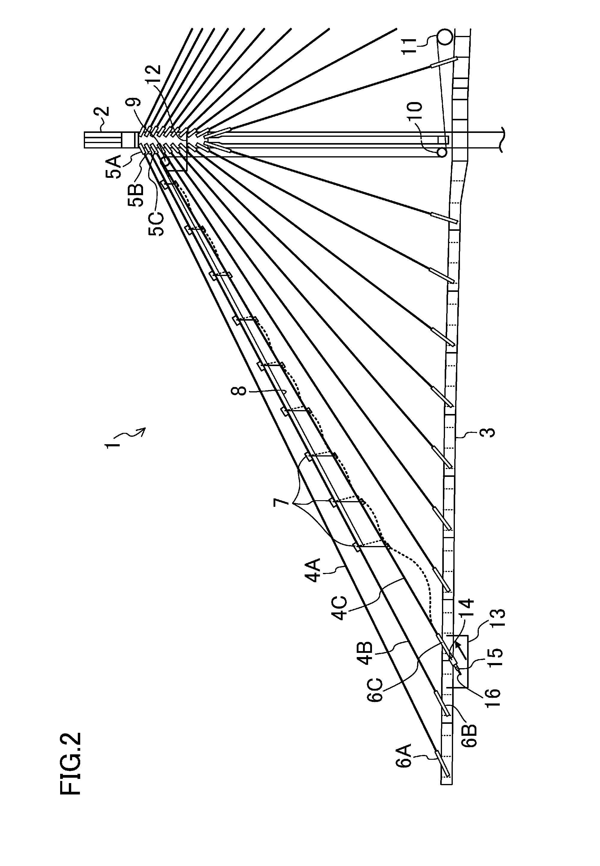
[0051]A method for replacing stay cables and a temporary hanger for replacing stay cables in one embodiment of the present invention will be described with reference to the drawings.

[0052]FIGS. 1-4 illustrate a procedure for removing a stay cable in the method of this embodiment.

[0053]FIG. 1 illustrates that a cable-stayed bridge 1 includes a vertical main tower 2, a horizontal bridge deck 3, and a plurality of stay cables 4A, 4B, 4C, etc. The bridge deck 3 crosses the main tower 2. The plurality of stay cables 4A, 4B, 4C, etc. are hung in tension and sloped with respect to the main tower 2 and the bridge deck 3. The stay cables 4A, 4B, 4C, etc. are fixed to the main tower 2 by anchor pipes 5A, 5B, 5C, etc. located on the main tower side, respectively. The stay cables 4A, 4B, 4C, etc. are also fixed to the bridge deck 3 by anchor pipes 6A, 6B, 6C, etc. located on the bridge deck side. That is, the bridge deck 3 is supported to the main tower 2 through the stay cables 4A, 4B, 4C, etc...


PUM


Abstract

A plurality of movable temporary hangers 7 are placed on a stay cable 4B hung in tension above a target stay cable 4C, and then the target stay cable 4C is held on a lower portion of the temporary hangers 7. Then, the target stay cable 4C held with the temporary hanger 7 is detached from a bridge deck 3 and a main tower 2. Then, the target stay cable 4C and the temporary hangers 7 holding the target stay cable 4C are moved toward the bridge deck 3 and removed.

Description

CROSS REFERENCE TO RELATED APPLICATIONS[0001]This application is a national stage application, filed under 35 U.S.C. §371, of International Application No. PCT / JP2013 / 002508, filed Apr. 12, 2013, which claims priority to and the benefit of Japanese Application No. 2012-126445, filed Jun. 1, 2012, the contents of all of which are hereby incorporated by reference in their entirety.BACKGROUND[0002]The present invention relates to a method for replacing stay cables that support a bridge deck to a main tower, and a temporary hanger for use in this method to replace stay cables.[0003]For example, a cable-stayed bridge is known as a bridge with a bridge deck supported to a main tower by stay cables.[0004]FIG. 16A illustrates a structure of a typical cable-stayed bridge. FIG. 16A illustrates that a cable-stayed bridge 101 includes a main tower 102, a bridge deck 103, and a plurality of stay cables 104. The main tower 102 is disposed vertically. The bridge deck 103 is disposed horizontally a...

Claims


Application Information

Patent Timeline
IPC IPC(8): E01D22/00F16L3/16
CPCF16L3/16E01D22/00E01D11/04
Inventor KAWABATA, SATOSHINAKAMURA, YOSHIHIKOYABUNO, MASASHI
Owner IHI INFRASTRUCTURE SYST CO LTD
Learn More