Method and device for manufacturing composite material parts

Active Publication Date: 2015-02-26
AIRBUS OPERATIONS SL
View PDF4 Cites 8 Cited by
  • Summary
  • Abstract
  • Description
  • Claims
  • Application Information

AI Technical Summary

Benefits of technology

[0002]The use of composite materials in part manufacturing for the aeronautical industry has

Problems solved by technology

This manufacturing method has the problem that when bending angles of approximately 90° in parts of big thickness, problems arise due to the fact that the carbon fibre is inextensible, which is why, in the bending area, there is a sliding between the different layers of prepreg material, which may not be sufficient to allow a coupling of some layers over others creating wrinkles.
These wrinkles are the reason why parts manufactured according to this traditional method do not comply with the quality requirements in

Method used


Image

  • Method and device for manufacturing composite material parts
  • Method and device for manufacturing composite material parts
  • Method and device for manufacturing composite material parts

Examples


Embodiment Construction

[0017]The invention discloses a method for manufacturing parts made of composite material from strips of prepreg material.

[0018]The manufacturing method object of the invention comprises the following stages:

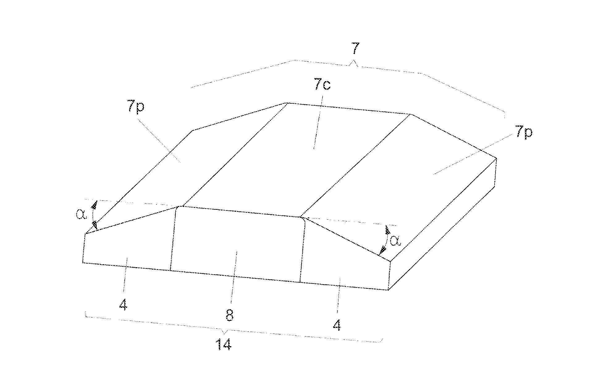
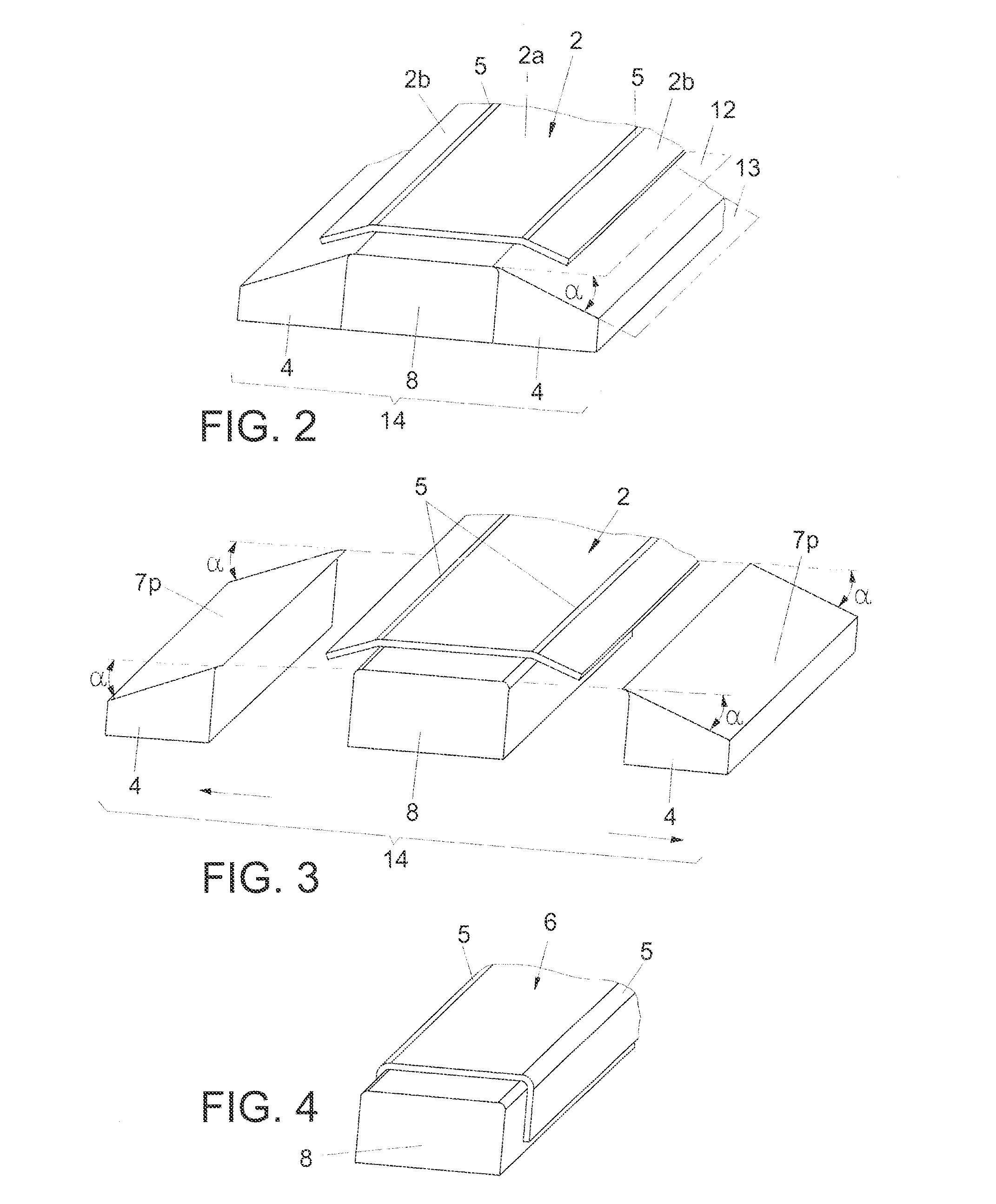
[0019]A) stacking of the prepreg material strips, on a laminating tool, so that a laminated part is obtained, comprising:[0020]a central section, contained in a first plane,[0021]at least one side section, contained in a second plane, and[0022]at least one bending axis between the central section and the, at least, one side section;

so that the first plane and the second plane form an angle α;

[0023]B) forming the laminated part by bending along the, at least one bending axis, the at least one side section with respect to the central section, obtaining a formed part;

[0024]C) curing the formed part.

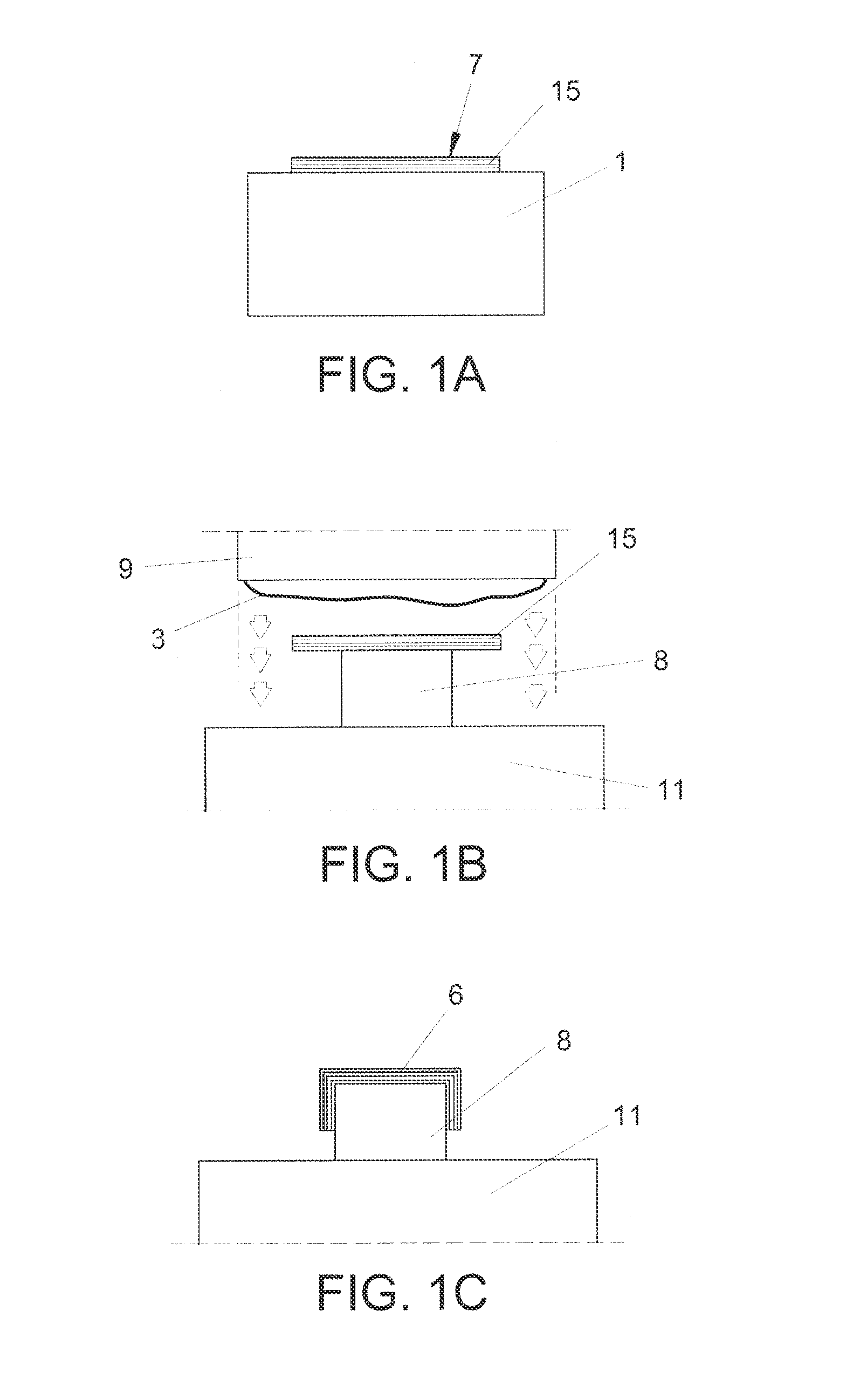
[0025]In the manufacturing method object of the invention, the stacking is carried out on a laminating tool comprising a male tool, on which the central section of the laminated part is ...


PUM

PropertyMeasurementUnit
Angleaaaaaaaaaa
Angleaaaaaaaaaa

Abstract

The manufacturing method object of the invention comprises the following stages: A) stacking strips of prepreg material on a laminating tool (14), so that an angled laminated part (2) is obtained comprising a central section (2a) contained in a first plane (12), at least one side section (2b) contained in a second plane (13), and at least one bending axis (5) between the central section (2a) and the at least one side section (2b), so that, the first plane and the second plane form an angle α; B) forming of the angled laminated part (2) comprising bending along the bending axis (5) the, at least, one side section with respect to the central section (2a), obtaining a formed part (6); C) curing, of the formed part (6).

Description


Claims


Application Information

Patent Timeline
Owner AIRBUS OPERATIONS SL
Why Eureka
Try Eureka