Drilling control and information system

a technology of information system and control method, applied in the direction of vibration device, survey, borehole/well accessories, etc., can solve the problems of reducing the life of the drill bit, maximizing the efficiency of one system, and having undesirable effects on other systems

Active Publication Date: 2015-02-26
NAT OILWELL VARCO LP
View PDF2 Cites 53 Cited by
  • Summary
  • Abstract
  • Description
  • Claims
  • Application Information

AI Technical Summary

Benefits of technology

[0013]In some embodiments, the method further comprises issuing the operating instruction from the drilling equipment controller to a mud pump and / or a choke. In some embodiments, the method further comprises issuing the operating instruction from the drilling equipment controller to a downhole control valve.

Problems solved by technology

One issue faced in the construction of wells is that maximizing the efficiency of one system may have undesirable effects on other systems.
For example, increasing the weight acting on the drill bit, known as weight on bit (WOB), may often result in an increased rate of penetration (ROP) and faster drilling but may also decrease the life of the drill bit, which may increase drilling time due to having to more frequently replace the drill bit.
Often these closed loop systems don't have the ability to monitor or consider the performance of all of the other systems being used or adjust the performance of multiple systems simultaneously.
Relying on human intervention may become complicated due to the fact that multiple parties are often involved in well construction.
Integrating multiple systems and companies becomes increasingly problematic as drilling processes advance in complexity.

Method used


Image

  • Drilling control and information system
  • Drilling control and information system
  • Drilling control and information system

Examples


Embodiment Construction

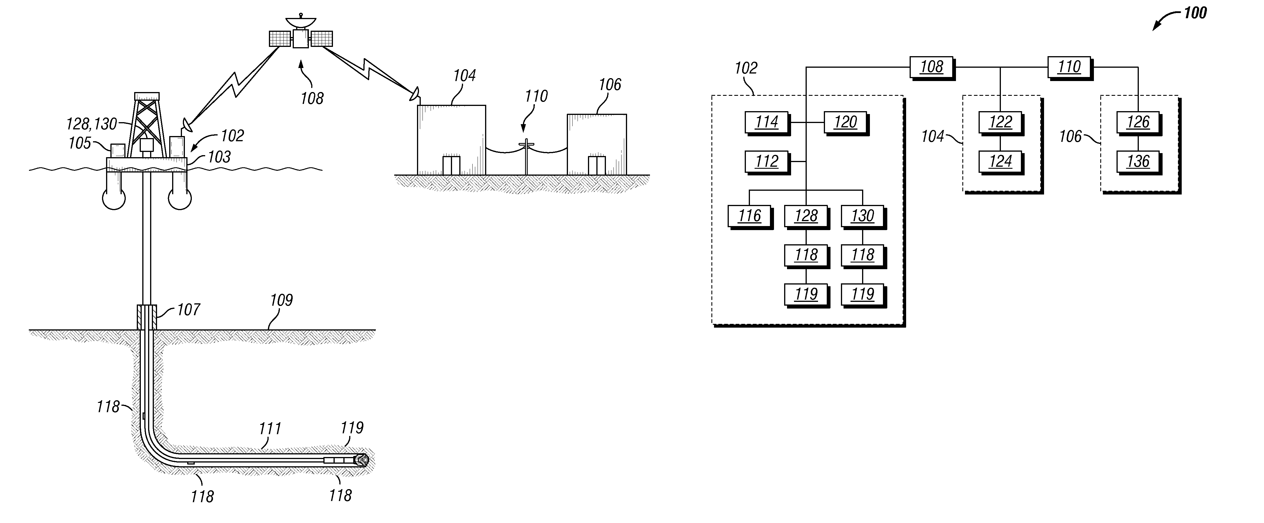
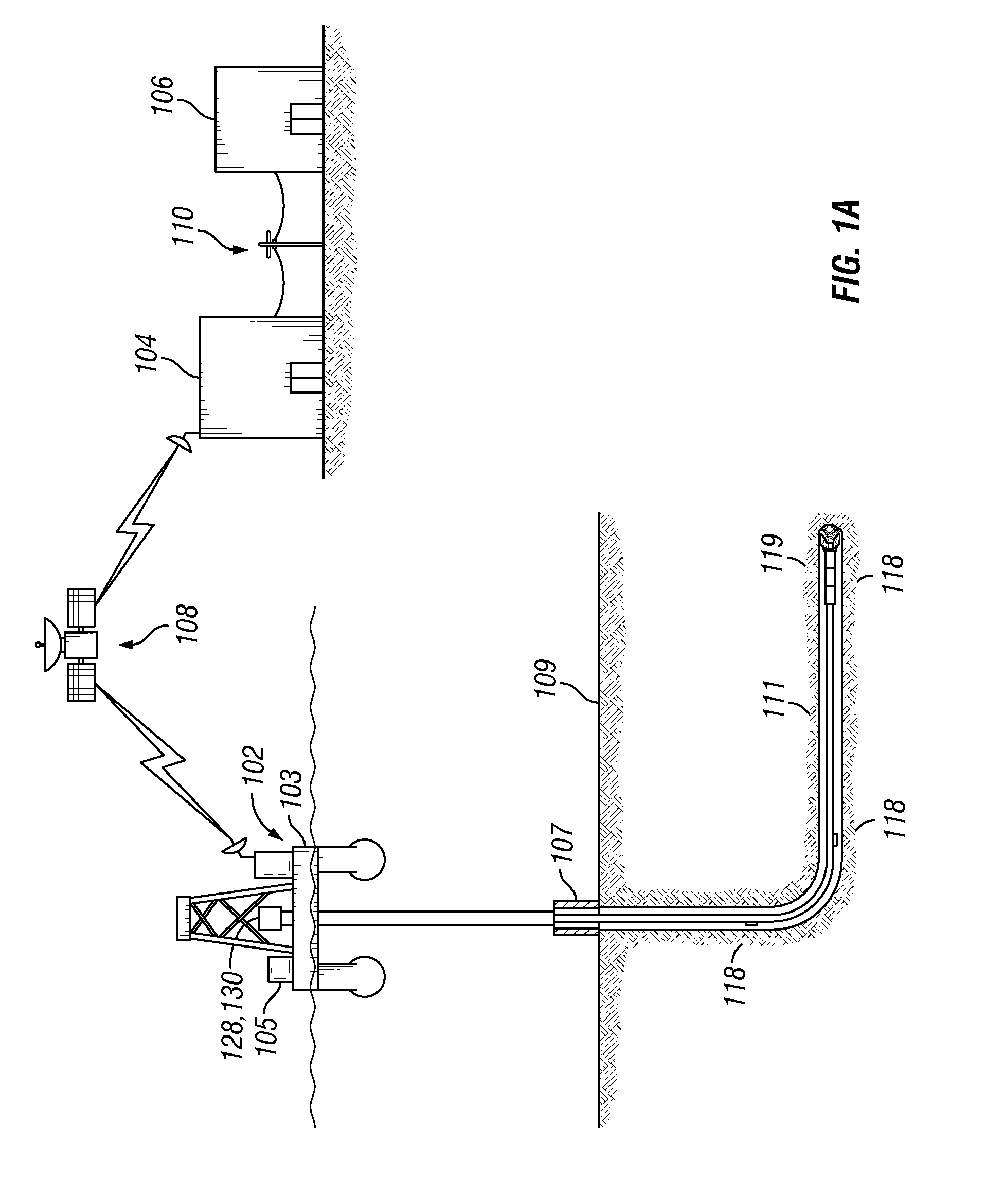
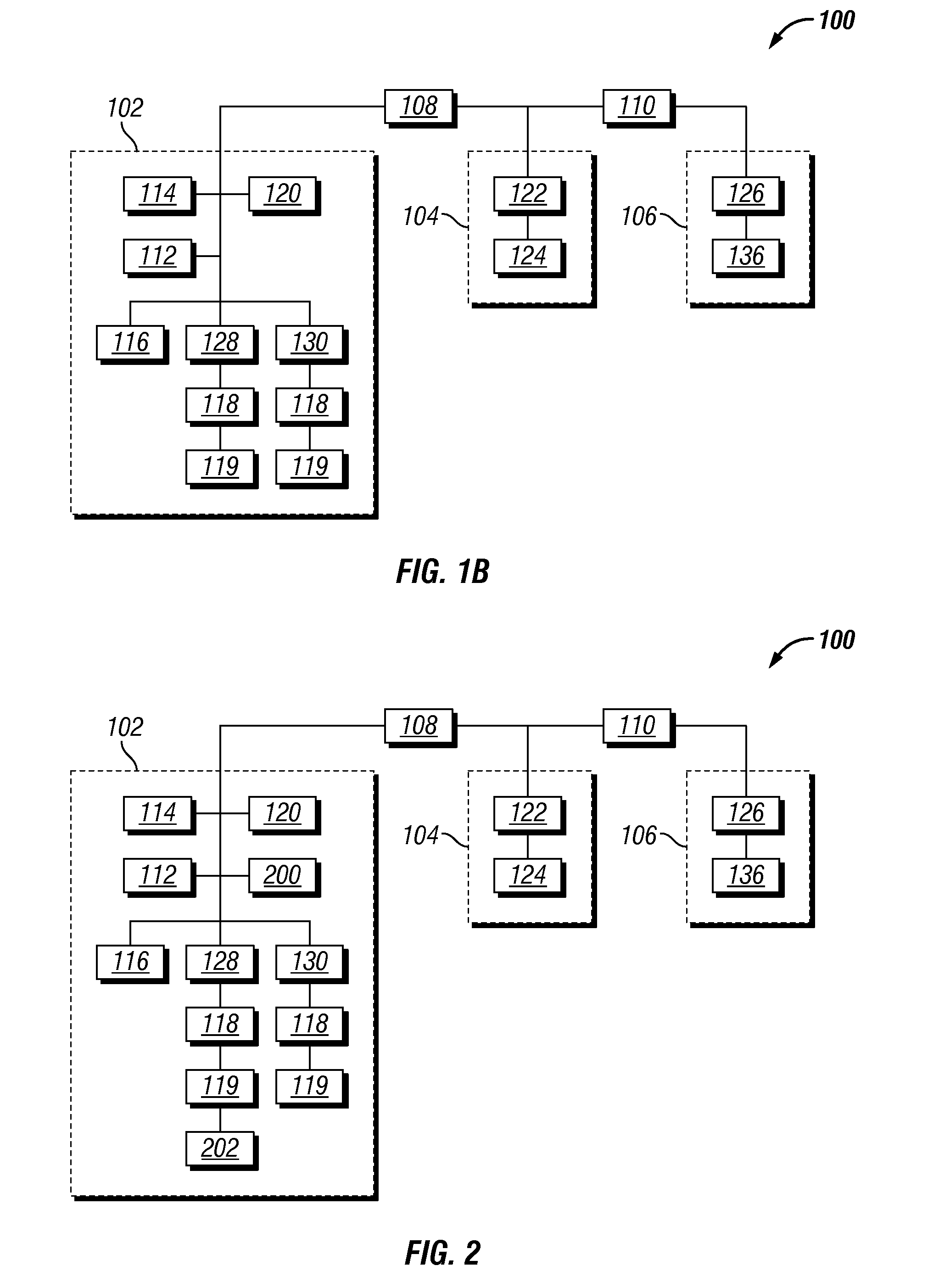
[0028]It is to be understood that the following disclosure describes several exemplary embodiments for implementing different features, structures, or functions of the invention. Exemplary embodiments of components, arrangements, and configurations are described below to simplify the present disclosure; however, these exemplary embodiments are provided merely as examples and are not intended to limit the scope of the invention. Additionally, the present disclosure may repeat reference numerals and / or letters in the various exemplary embodiments and across the Figures provided herein. This repetition is for the purpose of simplicity and clarity and does not in itself dictate a relationship between the various exemplary embodiments and / or configurations discussed in the various Figures. Moreover, the formation of a first feature over or on a second feature in the description that follows may include embodiments in which the first and second features are formed in direct contact, and m...


PUM


Abstract

A drilling control and information system comprising: a rig site network (102) including a drilling equipment controller (112) and a drilling parameter sensor (116); a downhole sensor (118) communicatively coupled to the rig site network; a data center (104) communicatively coupled to the rig site network; a remote access site (106) communicatively coupled to the data center; and a pressure management application (300) communicatively coupled to the rig site network, wherein the pressure management application receives pressure data from the drilling parameter sensor and the downhole sensor and issues an operating instruction to the drilling equipment controller.

Description

CROSS-REFERENCE TO RELATED APPLICATIONS[0001]This application claims benefit of U.S. Provisional Application Ser. No. 61 / 619,500 filed on Apr. 3, 2012, entitled “Drilling Control and Information System” and incorporated herein by reference in its entirety for all purposes.BACKGROUND[0002]This disclosure relates generally to methods and apparatus for drilling control and information systems. More specifically, this disclosure relates to methods and apparatus for providing drilling control and information systems that may interface with a plurality of control and information applications to support a variety of control and information functions through a common infrastructure. The common control infrastructure may be configured to acquire data from multiple sources, communicate that data with a plurality of control modules or information interfaces, and provide operating instructions to multiple drilling components.[0003]To recover hydrocarbons from subterranean formations, wells are ...

Claims


Application Information

Patent Timeline
Patent Type & Authority Applications(United States)
IPC IPC(8): E21B7/00E21B44/00E21B47/12E21B45/00E21B47/06
CPCE21B7/00E21B45/00E21B44/005E21B47/12E21B47/06E21B44/00E21B21/08E21B28/00E21B43/003E21B44/02E21B7/24E21B12/02E21B21/00E21B47/00
Inventor MEBANE, III, ROBERT EUGENE
Owner NAT OILWELL VARCO LP
Why Eureka
Try Eureka