Fuses

a technology of fuse and fuse body, applied in the field of fuse, can solve the problems of unwarranted complexity and achieve the effect of reducing the electric field enhancement factor

Inactive Publication Date: 2015-02-26
GE ENERGY POWER CONVERSION TECH
View PDF13 Cites 6 Cited by
  • Summary
  • Abstract
  • Description
  • Claims
  • Application Information

AI Technical Summary

Benefits of technology

[0020]Each fusible conductor element can have an associated electrostatic shield to suppress surface discharges and the potential formation of conductive streamers within the dielectric liquid. Each electrostatic shield can be formed from a metallised film, e.g. a metallised polypropylene film. The metallisation may be electrically connected to the terminals at the ends of the corresponding fusible conductor element by any convenient means. The shield metallisation is, therefore, connected electrically in parallel with the corresponding fusible conductor element.
[0021]Each electrostatic shield can be curved around the corresponding fusible conductor element. For example, each electrostatic shield can be in the form of a curved member with a radius about the longitudinal axis of the corresponding fusible conductor element. Each electrostatic shield can be held in position within the associated duct by its end terminations so that the profile of the shield is maintained along substantially its entire length. When the fuse assembly is immersed in a liquid dielectric then the radius r can be chosen to minimise the electric field enhancement factor in the liquid dielectric between the shields.

Problems solved by technology

However, these methods are optimised for high power systems and are therefore associated with a degree of complexity that would be un-warranted in the case of protective devices for use at relatively low currents.

Method used


Image

  • Fuses
  • Fuses
  • Fuses

Examples


Embodiment Construction

[0037]Throughout the following description, like components have been given the same reference numeral.

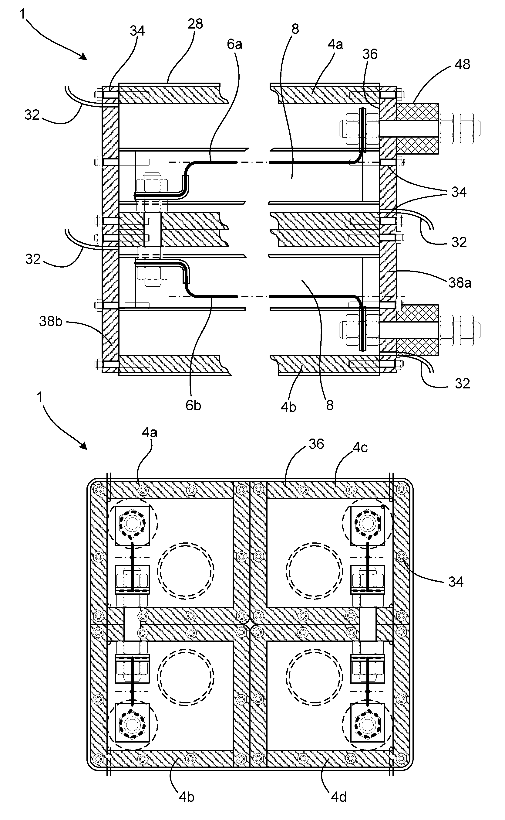
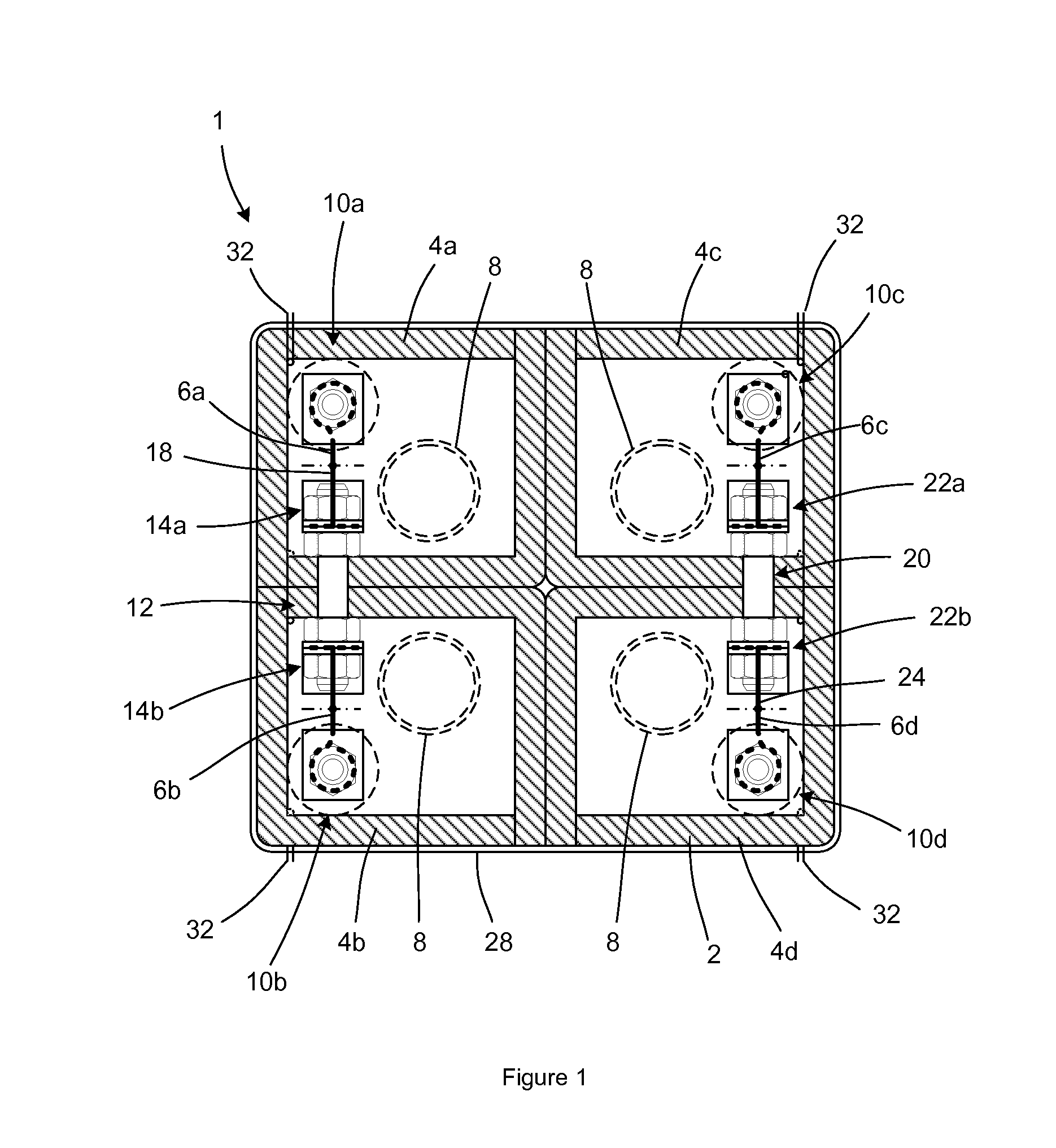
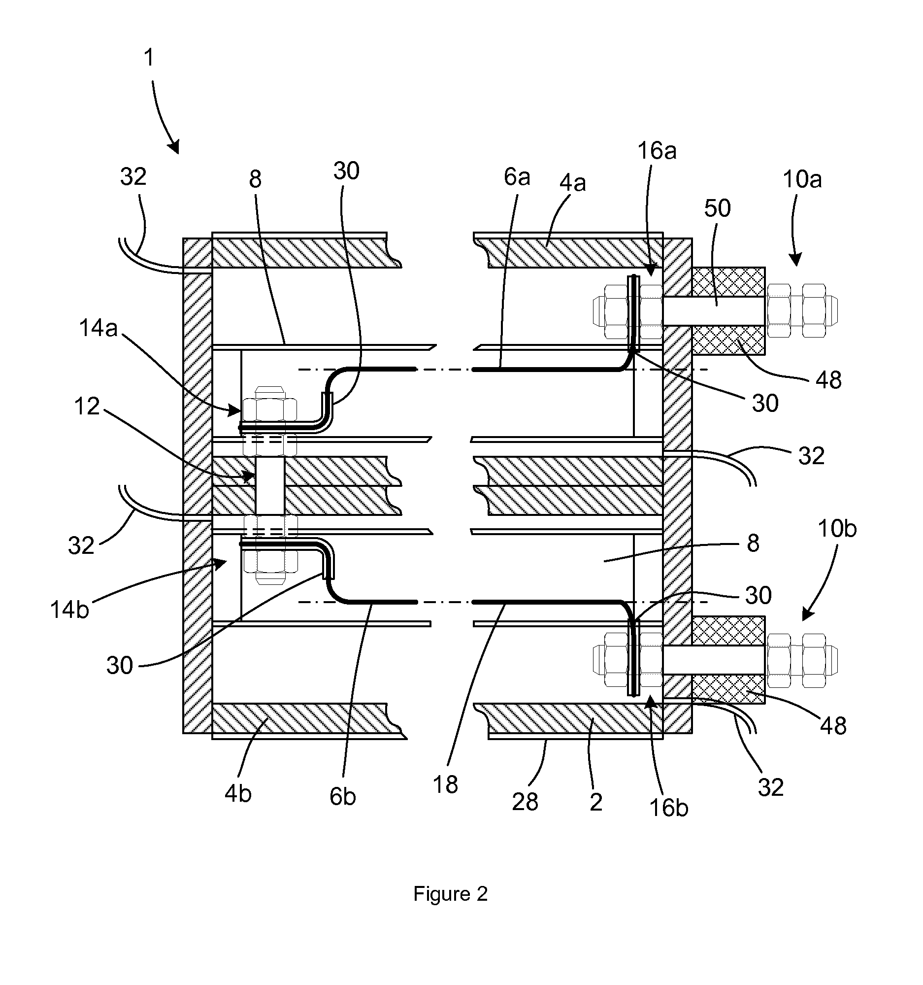
[0038]A fuse assembly 1 is shown in FIGS. 1 and 2 and includes a duct assembly 2 or housing with four ducts 4a, 4b, 4c, 4d in a 2×2 array. Each duct contains a fusible conductor element 6 (or fuse wire elements of circular cross section) and an accumulator 8 immersed in a liquid dielectric such as MIDEL 7131. More particularly, the interior of each duct 4a . . . 4d is filled with the liquid dielectric, such that the fusible conductor elements 6 and the accumulators 8 operate in a dielectric environment. The fusible conductor elements 6 extend substantially parallel to the longitudinal axis of the duct assembly 2. The fuse assembly 1, therefore, includes four fusible conductor elements 6a, 6b, 6c, 6d (i.e. n=2).

[0039]A first external terminal 10a is located at a first end of the first duct 4a. A second external terminal 10b is located at a first end of the second duct 4b. A first in...


PUM


Abstract

A fuse assembly for interrupting fault current in an external DC circuit. The fuse assembly includes 2n fusible conductor elements, where n is an integer, wherein the fusible conductor elements extend along, and are circumferentially around, a longitudinal axis of the fuse assembly. The fusible conductor elements are connected together in series to define fuse elements and the fusible conductor elements are orientated within the fuse assembly such that current flowing along each fusible conductor element is in the opposite direction to current flowing along the fusible conductor element or fusible conductor elements adjacent to it. The fuse assembly further includes a supply terminal connected to an end of the fuse element and connectible to a DC supply, and a load terminal connected to an opposite end of the first fuse element and connectible to an electrical load.

Description

TECHNICAL FIELD[0001]Embodiments of the present invention relate to fuses, and in particular, to fuses that can be used to interrupt fault current in an external DC circuit.BACKGROUND ART[0002]Fault-rated fuses that rupture and subsequently develop sufficient arc voltage in order to interrupt current flow in an external DC circuit are well known. It is also known that arc extinction in fuses is caused by the removal of heat from the arc by a number of cooling processes that are influenced by the nature of the material that surrounds the arc. These fuses and their underlying principles are described in ‘Electric Fuses’, A Wright & P G Newbery, 1982.[0003]It is known to extend the length of an arc by various deflection and barrier methods, thereby increasing the arc voltage that is attainable within a particular size of fuse assembly. However, these methods are optimised for high power systems and are therefore associated with a degree of complexity that would be un-warranted in the c...

Claims


Application Information

Patent Timeline
Patent Type & Authority Applications(United States)
IPC IPC(8): H01H85/50H01H85/40H01H85/00
CPCH01H85/50H01H2085/209H01H85/40H01H85/0039H01H85/0241H01H2085/025
Inventor BLEWITT, MARK WARRENCRANE, ALLAN DAVIDGOLDNEY, ANDREW
Owner GE ENERGY POWER CONVERSION TECH
Why Eureka
Try Eureka