Light guide plate with multi-directional structures

a multi-directional structure and light guide plate technology, applied in the direction of planar/plate-like light guides, lighting and heating apparatuses, instruments, etc., can solve the problems of poor luminance, and achieve the effect of promoting the uniformity of the overall light-emitting appearance of the light guide plate, promoting the uniformity of the overall light-emitting effect, and no additional cost burden

Active Publication Date: 2015-02-26
RADIANT OPTO ELECTRONICS
View PDF7 Cites 64 Cited by
  • Summary
  • Abstract
  • Description
  • Claims
  • Application Information

AI Technical Summary

Benefits of technology

[0008]One aspect of the present invention is to provide a light guide plate with multi-directional structures for simultaneously controlling light-emitting angles and optical trends of the light guide plate by alternately disposing first microstructures and second microstructures on the same plane of the light guide plate, thereby achieving light-mixing and more uniform light emitting effects. Furthermore, the uniformity of the overall light-emitting appearance of the light guide plate can be promoted by roughening or hazing surfaces of the first microstructures and second microstructures. In addition, the aforementioned first microstructures and second microstructures can be manufactured by using the existing microstructure processes or equipment without needing to additionally purchase new process equipment, and thus no additional cost burden is imposed to the manufacturing process.

Problems solved by technology

However, the surfaces with dotted microstructures are rough and may scatter the light, such that the light exiting from the light-emitting surface of the light guide plate has a non-uniform direction, and its light energy is not concentrated, thus further resulting poor luminance.

Method used


Image

  • Light guide plate with multi-directional structures
  • Light guide plate with multi-directional structures
  • Light guide plate with multi-directional structures

Examples


first embodiment

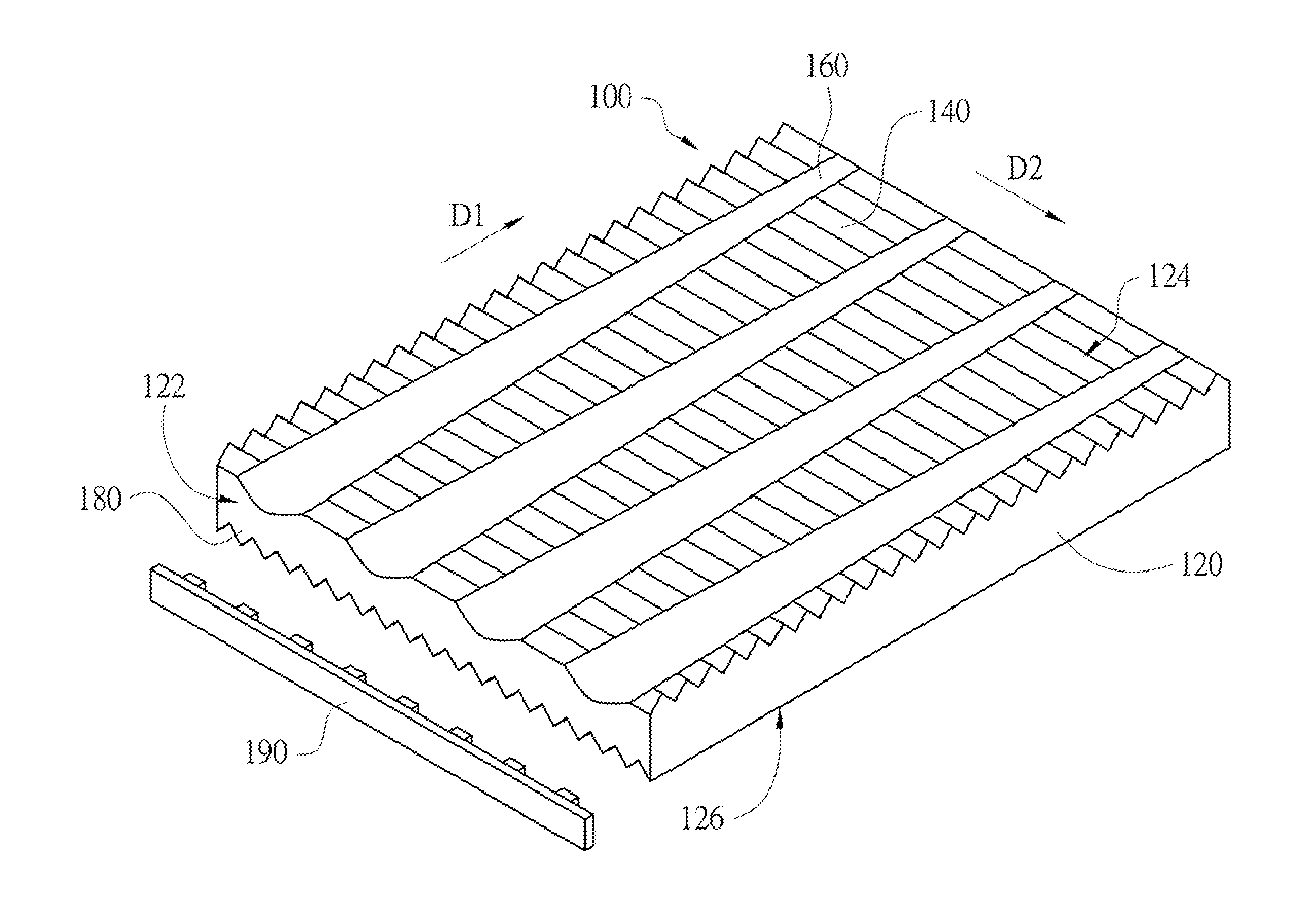
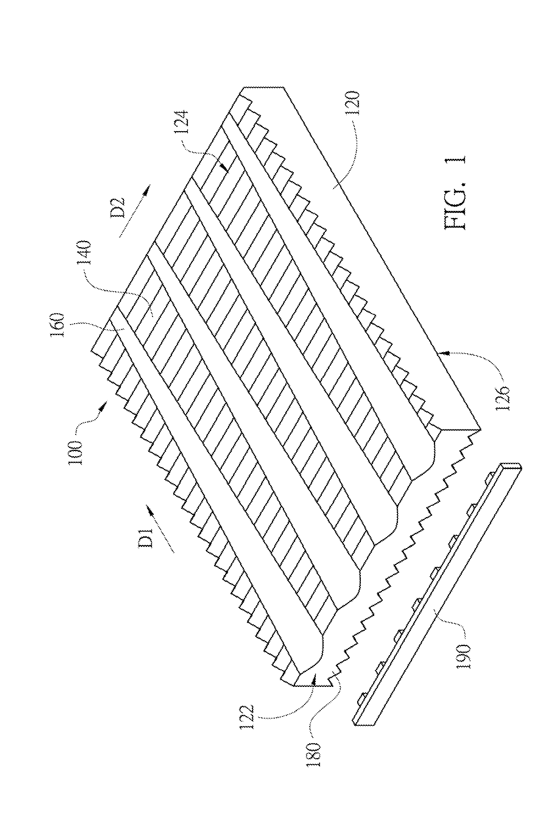
[0034]Referring to FIG. 1, FIG. 1 is a schematic structural diagram showing a light guide plate 100 with multi-directional structures in accordance with the present invention. The light guide plate 100 of the present embodiment may be applied to a backlight module (not shown). The light guide plate 100 may include a main body 120, a plurality of first microstructures 140 and a plurality of second microstructures 160. By disposing the first microstructures 140 and the second microstructures 160 on the main body 120, the light guide plate 100 can change and adjust light-emitting beam angles and optical trends of the light guide plate 100.

[0035]In the light guide plate 100, the main body 120 may be a transparent element or other equivalents. The main body 120 mainly includes at least one optical surface, such as a light-incident surface 122, a light-emitting surface 124 and a reflecting surface 126. The reflecting surface 126 and the light-emitting surface 124 are respectively located ...

second embodiment

[0042]Referring to FIG. 6, FIG. 6 is a schematic structural diagram showing a light guide plate 200 with multi-directional structures in accordance with the present invention. The light guide plate 200 of the present embodiment includes a main body 220, a plurality of first microstructures 240 and a plurality of second microstructures 260. The main body 220 mainly includes a light-incident surface 222, a light-emitting surface 224 and a reflecting surface 226. A light source 290 is disposed by the light-incident surface 222, and light emitted by the light source 290 may enter the light guide plate 200 from the light-incident surface 222. Each of the first microstructures 240 and each of the second microstructures 260 are convex portions protruding from the light-emitting surface 224. The cross-sectional profiles of the first microstructures 240 and the second microstructures 260 are respectively in inverted V-shape and arc-shape. Each of the first microstructures 240 is arranged on ...


PUM


Abstract

A light guide plate with multi-directional structures includes a main body, a plurality of first microstructures and a plurality of second microstructures. The main body includes a light-incident surface, a light-emitting surface and a reflecting surface. The light-incident surface connects the light-emitting surface and the reflecting surface. The first microstructures are disposed on the light-emitting surface or the reflecting surface and arranged along a first extending direction. The second microstructures are disposed on the light-emitting surface or the reflecting surface and arranged along a second extending direction. The second microstructures and the first microstructures are disposed on the same plane and intersect with each other. Each of the second microstructures is a single stripe pattern, and has a width which becomes gradually smaller from one end of the second microstructure near the light-incident surface to the other end of the second microstructure away from the light-incident surface.

Description

RELATED APPLICATIONS[0001]This application claims priority to Taiwan Application Serial Number 102129835, filed Aug. 20, 2013, which is herein incorporated by reference.BACKGROUND[0002]1. Field of Invention[0003]The present invention relates to a light guide plate. More particularly, the present invention relates to a light guide plate with multi-directional structures.[0004]2. Description of Related Art[0005]A light guide plate has a light-incident surface, a light-emitting surface and a reflecting surface. Light emitted by a light source enters the light guide plate from the light-incident surface, and exits from the light-emitting surface. In order to mix the light pass through the light guide plate uniformly, microstructures (such as dotted microstructures or striped microstructures, a.k.a. lenticular microstructures) are generally disposed on the light-emitting surface or the reflecting surface of the light guide plate. However, the surfaces with dotted microstructures are roug...

Claims


Application Information

Patent Timeline
Patent Type & Authority Applications(United States)
IPC IPC(8): F21V8/00
CPCG02B6/0016G02B6/0036G02B6/0038G02B6/0061
Inventor CHANG, CHIA-YINHUANG, PO-CHANGCHANG, CHIH-CHIANGCHANG, SHAN-FULIN, SHIN-BO
Owner RADIANT OPTO ELECTRONICS
Why Eureka
Try Eureka