Pogo pin connector

Inactive Publication Date: 2015-02-26
CHENG UEI PRECISION IND CO LTD
View PDF0 Cites 8 Cited by
  • Summary
  • Abstract
  • Description
  • Claims
  • Application Information

AI Technical Summary

Benefits of technology

[0006]As described above, the pogo pins and the corresponding contact terminals are connected with each other by riveting the riveted flanges and the fixing strips together. In use, the pogo pin connector utilizes the elastic contact arms of the contact terminals to elastically press against a printed circuit board so a

Problems solved by technology

However, the process of utilizing the reflow soldering to solder the pogo pin connector with the printed circuit board easily brings about some adverse effects, such as deformation and bubble of

Method used


Image

  • Pogo pin connector
  • Pogo pin connector
  • Pogo pin connector

Examples


Example

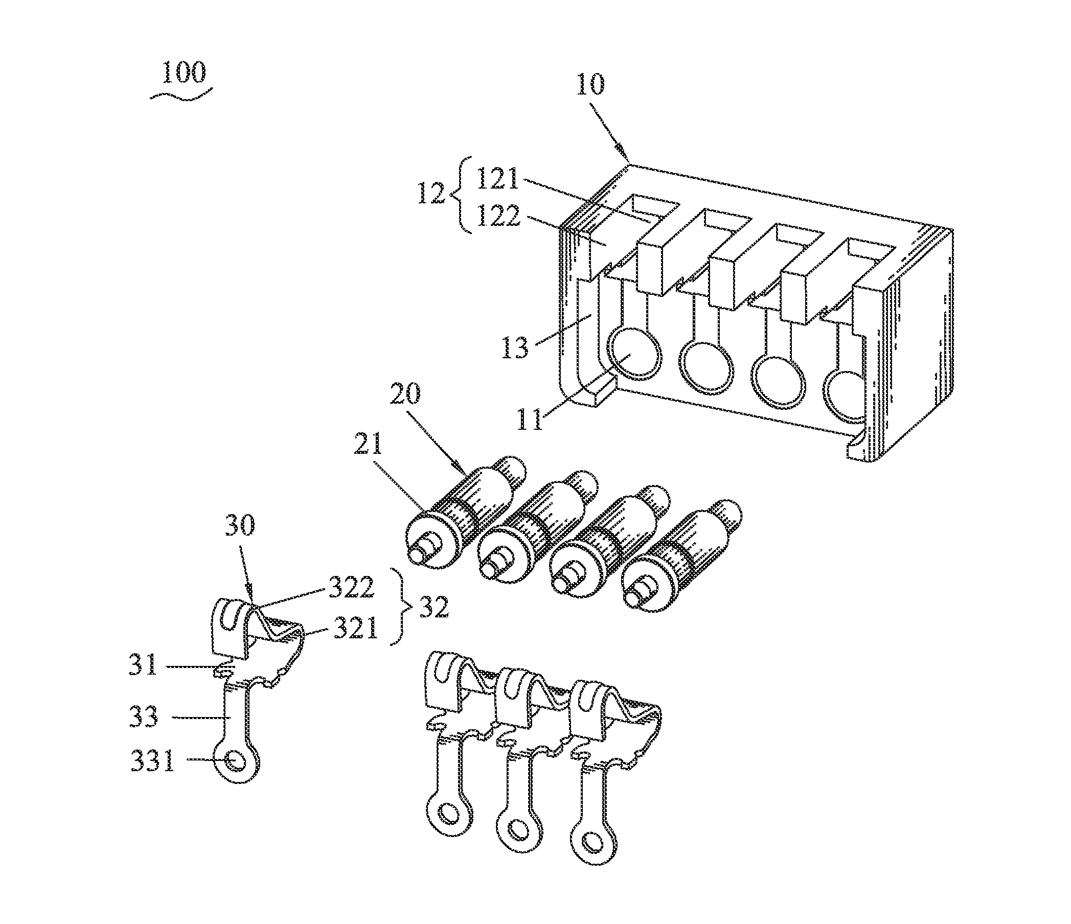
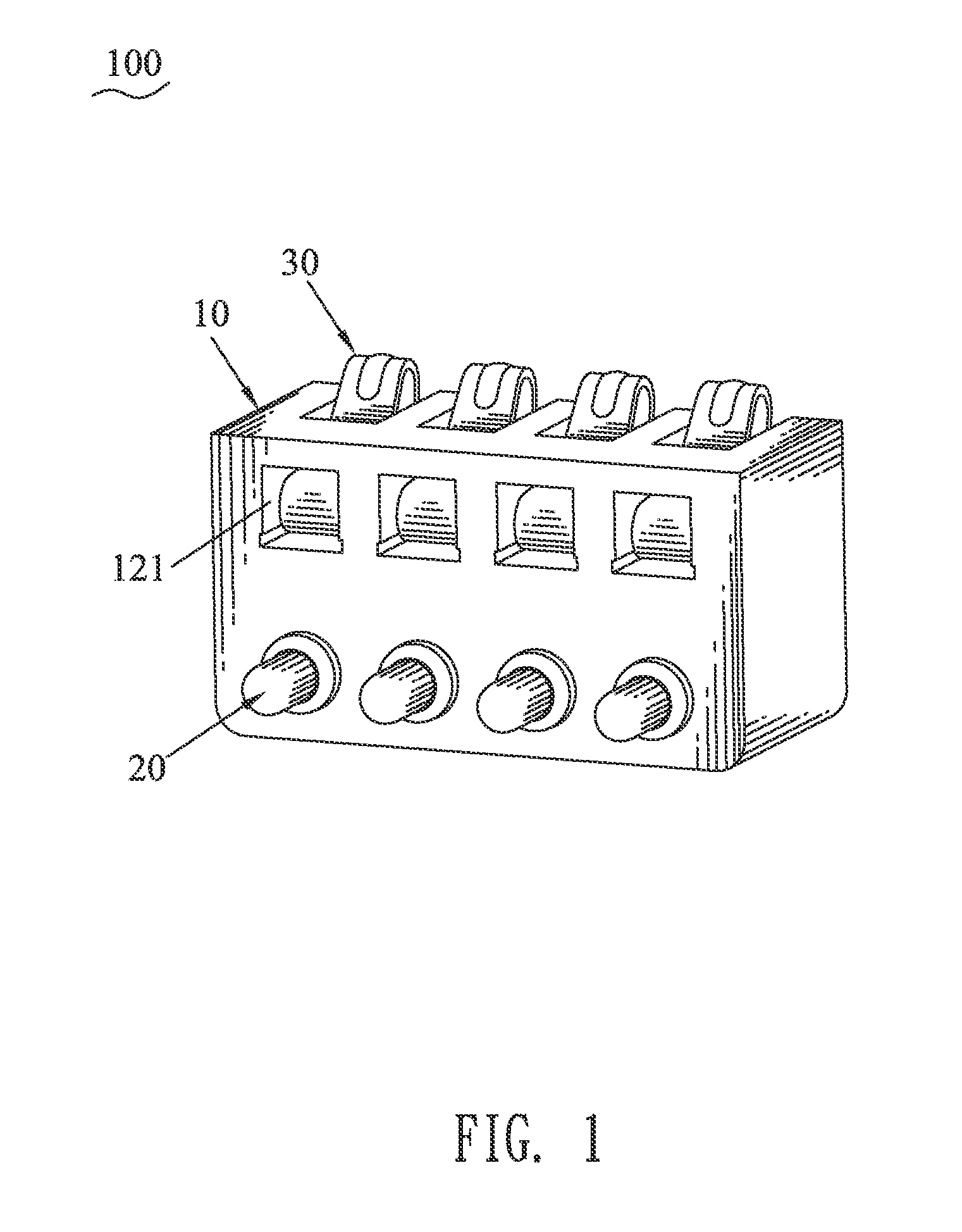
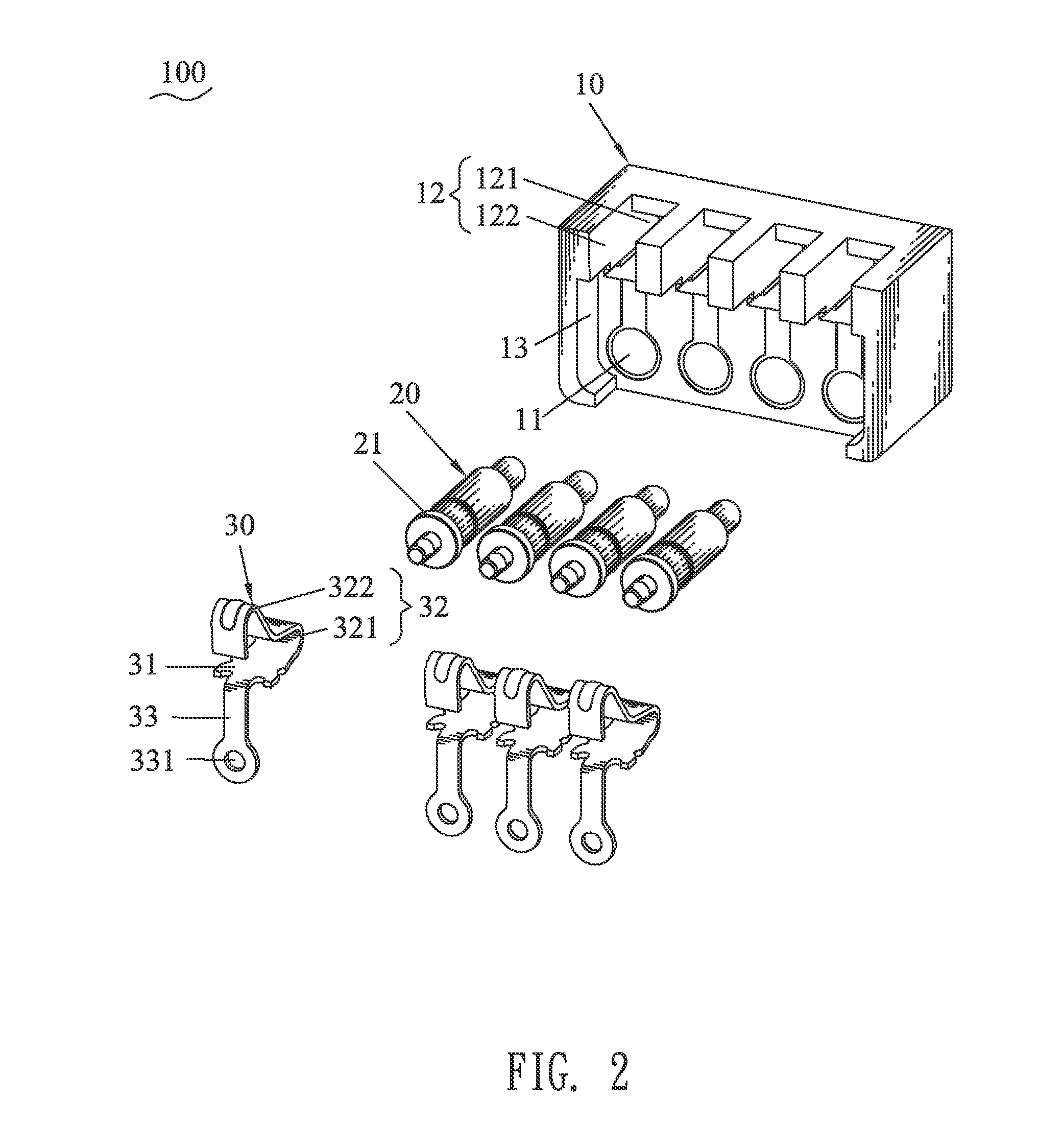
[0011]Referring to FIG. 1, FIG. 2 and FIG. 3, a pogo pin connector 100 according to an embodiment of the present invention includes an insulating housing 10, a plurality of pogo pins 20 and a plurality of contact terminals 30 assembled in the insulating housing 10 respectively.

[0012]The insulating housing 10 defines a plurality of receiving passageways 11 at a lower part thereof and a plurality of receiving grooves 12 at a top thereof. The pogo pins 20 are inserted forward in the receiving passageways 11 of the insulating housing 10. Front ends of the pogo pins 20 retractably project beyond a front face of the insulating housing 10. A rear end of each of the pogo pins 20 protrudes outward to form a riveted flange 21. The contact terminals 30 are assembled forward in the receiving grooves 12 of the insulating housing 10. Each of the contact terminals 30 has a fastening plate 31 placed levelly, an elastic contact arm 32 curvedly extending upward from a front end of the fastening plate...


PUM


Abstract

A pogo pin connector includes an insulating housing, a plurality of pogo pins and contact terminals assembled forward in the insulating housing respectively. Front ends of the pogo pins retractably project beyond a front face of the insulating housing. A rear end of each of the pogo pins protrudes outward to form a riveted flange. Each of the contact terminals has a fastening plate placed levelly, an elastic contact arm curvedly extending upward from a front end of the fastening plate to elastically project beyond a top face of the insulating housing, and a fixing strip extending downward from a rear end of the fastening plate with a through hole being opened in a bottom end thereof. The rear ends of the pogo pins pass through the through holes of the contact terminals respectively to make the riveted flanges and the corresponding fixing strips riveted together.

Description

BACKGROUND OF THE INVENTION[0001]1. Field of the Invention[0002]The present invention relates to an electrical connector, and more particularly to a pogo pin connector.[0003]2. The Related Art[0004]Conventionally, a pogo pin connector includes an insulating housing and a plurality of pogo pins assembled in the insulating housing. In use, the pogo pin connector is often soldered with a printed circuit board by reflow soldering. The reflow soldering is carried out by a series of operations such as high temperature. However, the process of utilizing the reflow soldering to solder the pogo pin connector with the printed circuit board easily brings about some adverse effects, such as deformation and bubble of the insulating housing, and could cause the loss of elasticity of the pogo pins after stress release of the reflow soldering. As a result, that reduces the service life of the pogo pin connector.SUMMARY OF THE INVENTION[0005]An object of the present invention is to provide a pogo pi...

Claims


Application Information

Patent Timeline
IPC IPC(8): H01R13/24
CPCH01R13/24H01R13/2421H01R13/2442
Inventor CHEN, YUNG YILAI, MING CHUN
Owner CHENG UEI PRECISION IND CO LTD
Why Eureka
Try Eureka