Patient positioning support structure

a positioning support and patient technology, applied in the field of patient positioning support structures, can solve problems such as unwanted consequences, and achieve the effects of convenient use, convenient use, and low cos

Inactive Publication Date: 2015-03-05
JACKSON ROGER P
View PDF23 Cites 78 Cited by
  • Summary
  • Abstract
  • Description
  • Claims
  • Application Information

AI Technical Summary

Benefits of technology

[0029]Therefore, it is an object of the present invention to overcome one or more of the problems with patient support systems described above. Further objects of the present invention include providing breaking or hinged patient support structures; providing such structures wherein such break or joint may be in any desired direction; providing such structures that include at least one base support structure that allows for vertical height adjustment; providing such a structure wherein such base support is located at both outer ends of the patient support, allowing for patient positioning and clearance for access to the patient in a wide variety of orientations; providing such a structure that may be rotated about an axis as well as moved upwardly or downwardly at either end thereof; and providing apparatus and methods that are easy to use and especially adapted for the intended use thereof and wherein the apparatus are comparatively inexpensive to make and suitable for use.
[0030]Other objects and advantages of this invention will become apparent from the following description taken in conjunction with the accompanying drawings wherein are set forth, by way of illustration and example, certain embodiments of this invention.
[0031]The drawings constitute a part of this specification and include exemplary embodiments of the present invention and illustrate various objects and features thereof.

Problems solved by technology

While manipulation of the patient when on the support structure suspended between outer end supports of the base is desirable, too much vertical and horizontal travel for the patient is not, as this can lead to unwanted consequences concerning anaesthesia, tubing, IV lines in the patient, and son on.

Method used


Image

  • Patient positioning support structure
  • Patient positioning support structure
  • Patient positioning support structure

Examples


Embodiment Construction

[0086]As required, detailed embodiments of the present invention are disclosed herein; however, it is to be understood that the disclosed embodiments are merely exemplary of the invention, which may be embodied in various forms. Therefore, specific structural and functional details disclosed herein are not to be interpreted as limiting, but merely as a basis for the claims and as a representative basis for teaching one skilled in the art to variously employ the present invention in virtually any appropriately detailed structure.

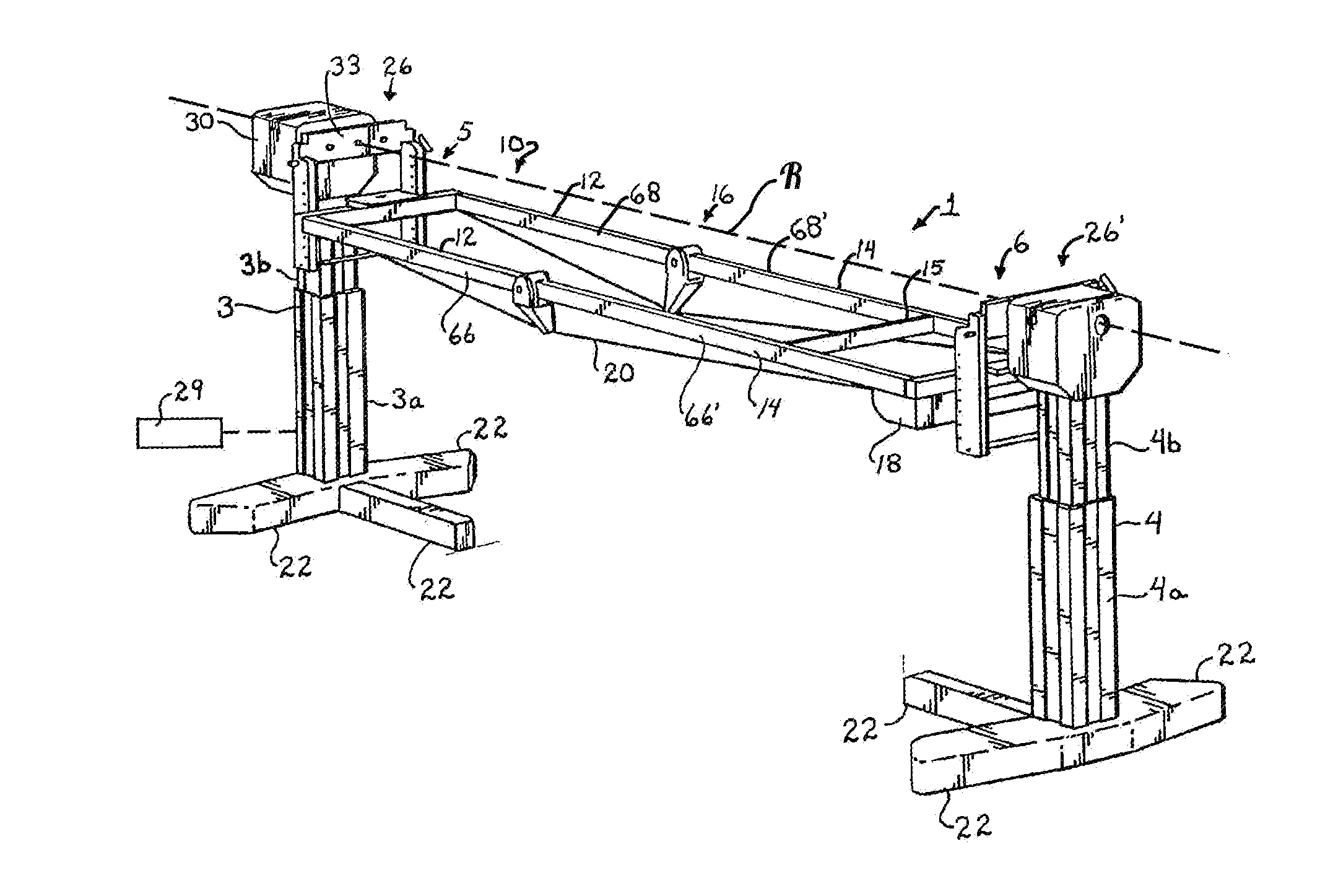
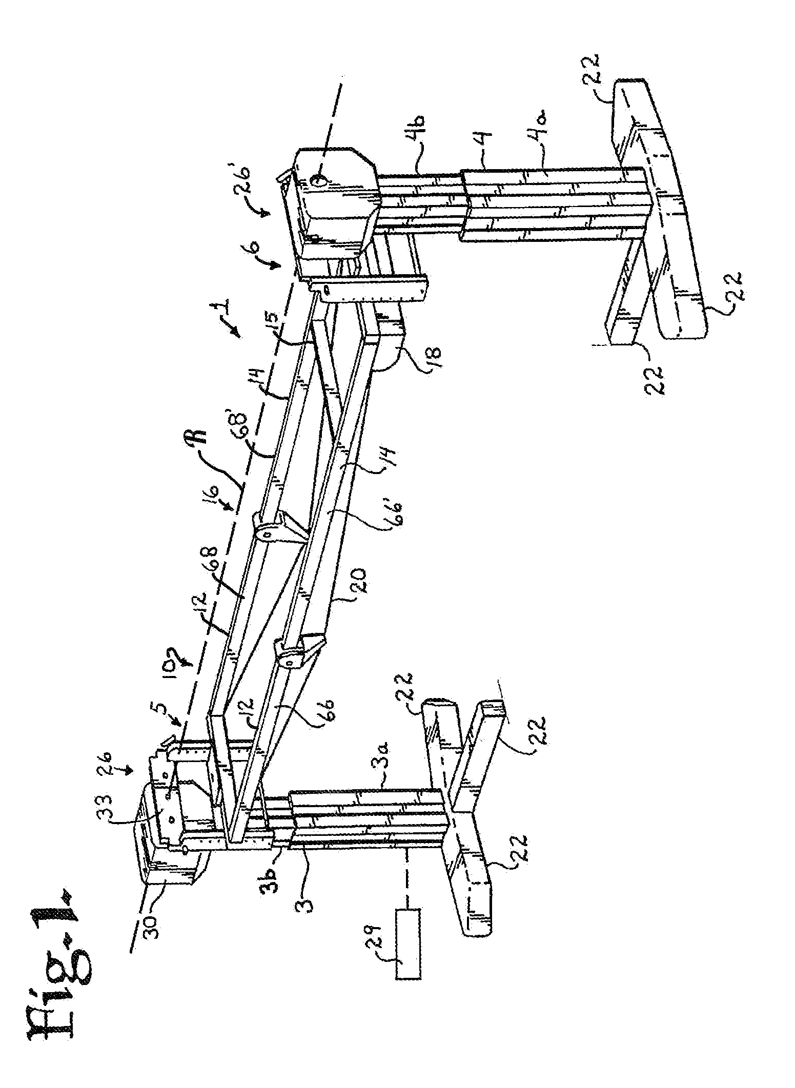
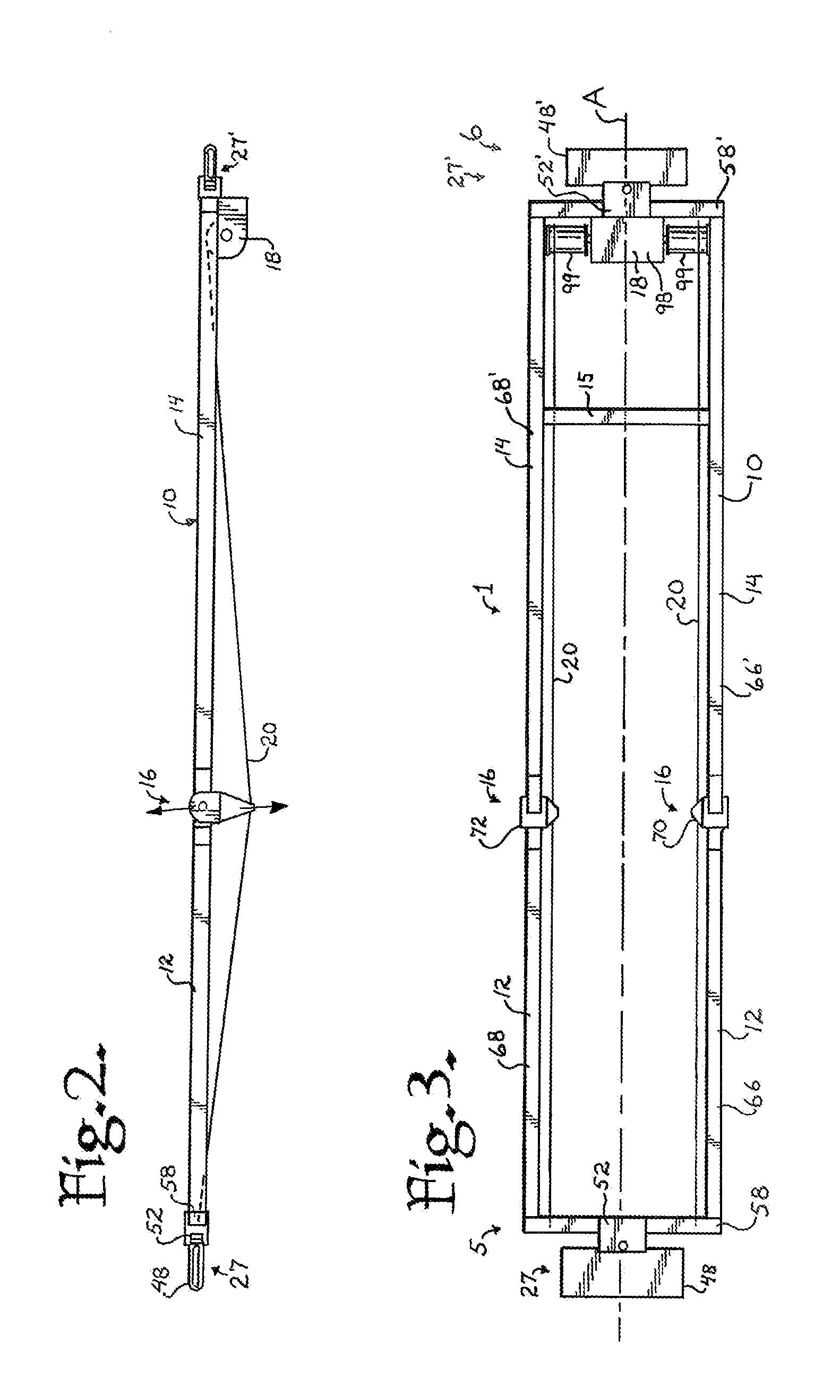
[0087]Referring now to the drawings, a patient positioning support structure according to the invention is generally designated by the reference numeral 1 and is depicted in FIGS. 1-12. The structure 1 includes first and second support piers or column assemblies 3 and 4 which are illustrated as independent, stationary floor base support structures as shown in FIG. 1 or may be connected to one another by a base support as illustrated in the embodiment shown in...


PUM


Abstract

A patient support system includes independently adjustable end columns supporting a centrally hinged, jointed or breaking patient support structure. At least one column includes a powered rotation assembly. The patient support includes at least two sections. A coordinated drive system provides for both upwardly and downwardly breaking or jointed orientations of the two sections in various inclined and tilted positions. Cable, cantilevered and pull-rod systems are included.

Description

CROSS-REFERENCE TO RELATED APPLICATIONS[0001]This application is a continuation-in-part of U.S. Ser. No. 14 / 096,875, filed Dec. 4, 2013, and which is a continuation of U.S. Ser. No. 13 / 317,012, filed Oct. 6, 2011, now U.S. Pat. No. 8,719,979, all of which are incorporated by reference herein. U.S. Ser. No. 13 / 317,012 is a continuation of U.S. Ser. No. 12 / 460,702, filed Jul. 23, 2009, now U.S. Pat. No. 8,060,960, which is a continuation of U.S. Ser. No. 11 / 788,513, filed Apr. 20, 2007, now U.S. Pat. No. 7,565,708, which claimed the benefit of U.S. Provisional Application No. 60 / 798,288 filed May 5, 2006 and was also a continuation-in-part of pending U.S. patent application Ser. No. 11 / 159,494 filed Jun. 23, 2005, now U.S. Pat. No. 7,343,635, that is a continuation-in-part of U.S. patent application Ser. No. 11 / 062,775 filed Feb. 22, 2005, now U.S. Pat. No. 7,152,261, all of which are incorporated by reference herein. This application is a continuation-in-part of U.S. Ser. No. 14 / 050,...

Claims


Application Information

Patent Timeline
Patent Type & Authority Applications(United States)
IPC IPC(8): A61G13/04A61G13/06
CPCA61G13/06A61G13/04A61B6/0407A61G7/001A61G7/008A61G13/0036A61G13/02A61G13/08A61G2200/325A61G13/0054A61G13/104
Inventor JACKSON, ROGER P.
Owner JACKSON ROGER P
Why Eureka
Try Eureka