


Quick Research
Generate reliable direction feasibility study reports for your R&D in just a few steps.

Technical Q&A
Discover and master advanced knowledge NOW. Basics, ideas, possibilities, all at once.

Find Solutions
As an expert in R&D theories, this can generate solutions to your technical problems instantly.

Evaluate Feasibility
Analyze your overall solution with one click, know your potential R&D risks in advance.

Monitor Landscape
Get weekly tech updates, stay abreast of the latest tech innovations and key insights.
Production method of scintillator array
a production method and scintillator technology, applied in the direction of radiation intensity measurement, instruments, x/gamma/cosmic radiation measurement, etc., can solve the problems of increased steps, large number of steps, and method that does not use adhesive sheets for fixing comb-shaped scintillator wafers, etc., to achieve efficient production of scintillator arrays and high precision
- Summary
- Abstract
- Description
- Claims
- Application Information
AI Technical Summary
Benefits of technology
Problems solved by technology
Method used
Image

Examples
first embodiment
(1) First Embodiment
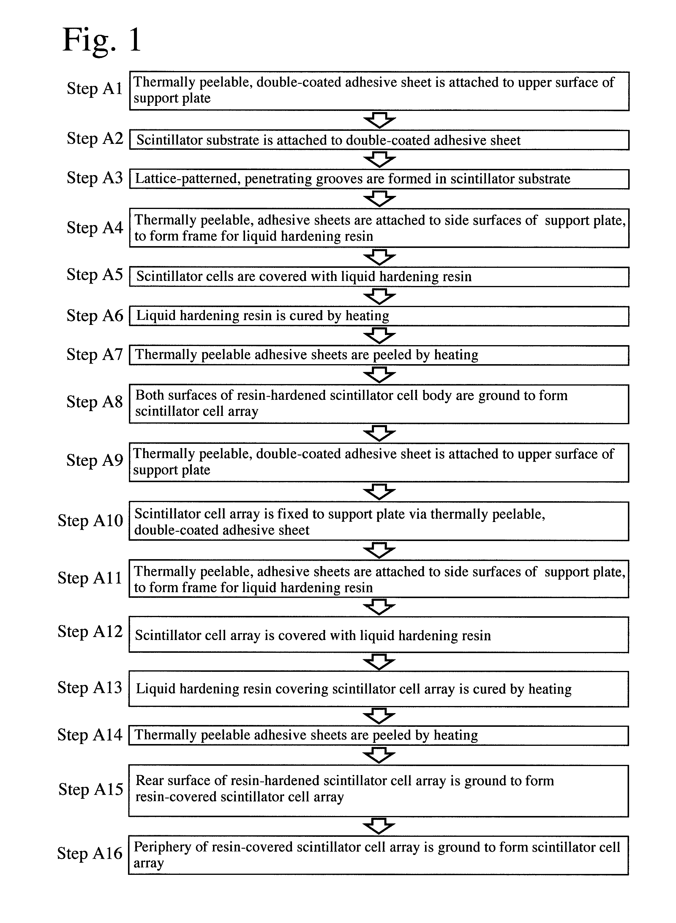
[0072]FIG. 1 is a flowchart showing the production method of the first embodiment. First prepared is a thermally peelable, double-coated adhesive sheet constituted by a base film having first and second adhesive surfaces on both sides, at least the second adhesive surface being a thermally peelable adhesive layer, and each adhesive layer being covered with a separator. When the thermally peelable adhesive layer is heated to a predetermined temperature, it is foamed to have decreased adhesion, so that it becomes easily peelable. The first adhesive layer is also preferably a thermally peelable adhesive layer foamable at the same temperature as that of the second adhesive surface.
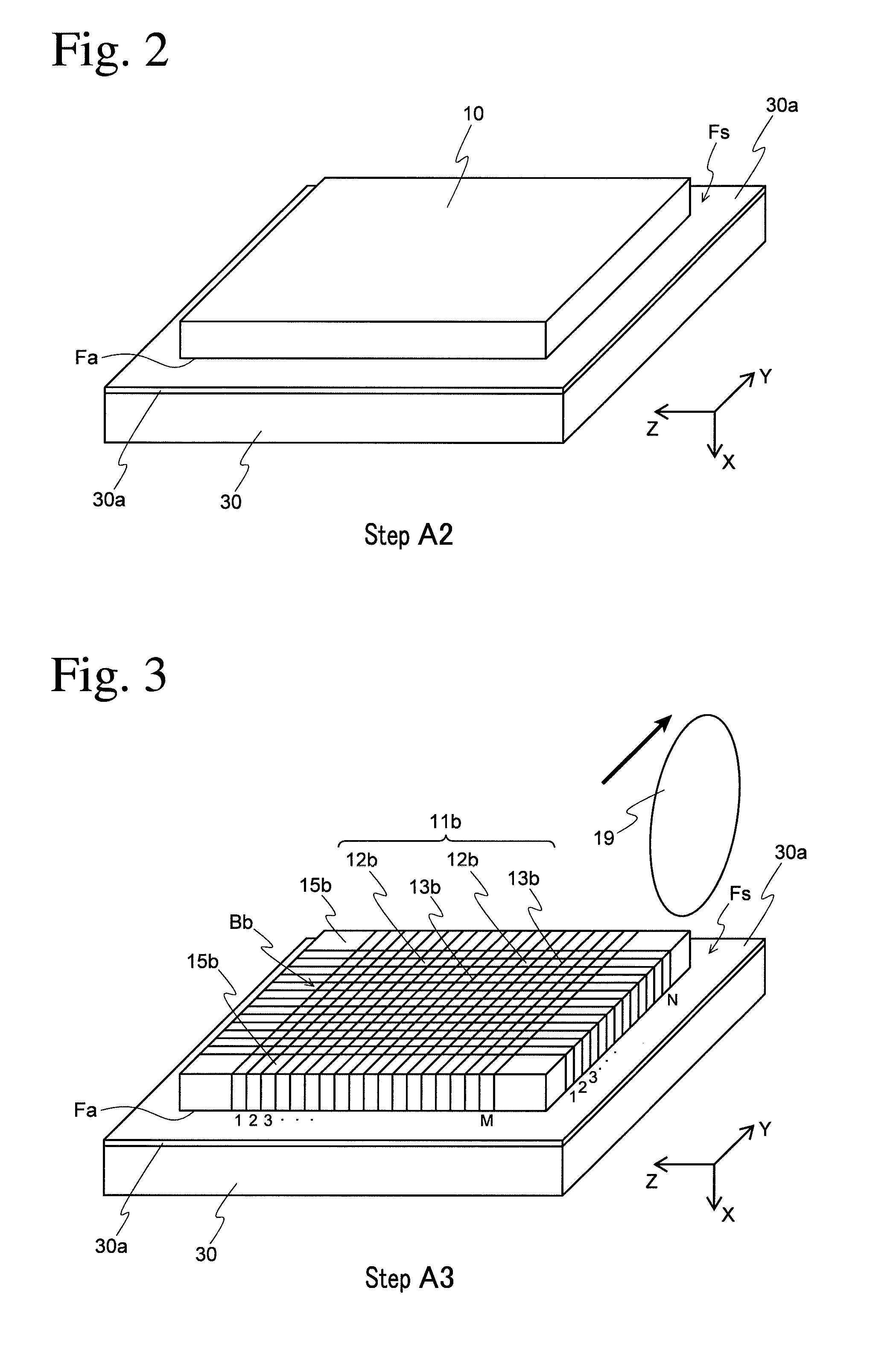
[0073]As shown in FIG. 2, a separator is peeled from the first adhesive surface of the thermally peelable, double-coated adhesive sheet 30a as wide as covering an upper surface of the support plate 30, and the exposed first adhesive surface is attached to the upper surface of the support pl...
second embodiment
(4) Second Embodiment
[0094]The method in the second embodiment is characterized by forming unpenetrating grooves in place of the penetrating grooves. As shown in FIG. 14, steps B1 and B2 for fixing the scintillator substrate 10 to the support plate 30 via a thermally peelable, double-coated adhesive sheet 30a are the same as the steps A1 and A2 in the first embodiment.
[0095]As shown in FIG. 15, pluralities (M×N) of parallel, unpenetrating grooves 13b′ as deep as not reaching the thermally peelable, double-coated adhesive sheet 30a are formed in a perpendicular lattice pattern in the scintillator substrate 10 excluding both end portions 15b, 15b by a rotating cutting grinder 19 (step B3). Remaining in the scintillator substrate 10 after the formation of the unpenetrating grooves 13b′ are connecting portions 11c supporting scintillator cells 12b. The thickness of the connecting portions 11c is properly set, such that the scintillator cells are not cracked by the thermal curing of a li...
third embodiment
(4) Third Embodiment
[0100]The method in the third embodiment is different from the method in the second embodiment in the direction (vertical direction) of a scintillator substrate with lattice-patterned, unpenetrating grooves, which is fixed to a support plate via a thermally peelable, double-coated adhesive sheet. Accordingly, as shown in FIG. 18, steps C1-C4 up to the peeling of a scintillator substrate 11b′ with lattice-patterned, unpenetrating grooves from a thermally peelable, double-coated adhesive sheet 30a on a support plate 30 by heating to the second temperature are the same as the steps B1-B4 in the second embodiment. Because a reflecting resin is not used to fill lattice-patterned, unpenetrating grooves directly after the scintillator substrate 10 is fixed, a thermally peelable, double-coated adhesive sheet need not be used to fix the scintillator substrate 10. Accordingly, other adhesive sheets than the thermally peelable, double-coated adhesive sheet, adhesives, etc. ...
PUM
| Property | Measurement | Unit |
|---|---|---|
| surface roughness Ra | aaaaa | aaaaa |
| height | aaaaa | aaaaa |
| aspect ratio w/t | aaaaa | aaaaa |
Abstract
Description
Claims
Application Information
 - R&D Engineer
- R&D Manager
- IP Professional
- Industry Leading Data Capabilities
- Powerful AI technology
- Patent DNA Extraction
Browse by: Latest US Patents, China's latest patents, Technical Efficacy Thesaurus, Application Domain, Technology Topic, Popular Technical Reports.
© 2024 PatSnap. All rights reserved.Legal|Privacy policy|Modern Slavery Act Transparency Statement|Sitemap|About US| Contact US: help@patsnap.com