
Work Machine

a technology of working machine and counterweight, which is applied in the direction of machines/engines, mechanical equipment, transportation and packaging, etc., can solve the problems of affecting the stability of the machine, the inability to secure the space, and the inability of small machines such as compact excavators to achieve the effect of avoiding discomfort and suppressing the heating of the counterweigh

Active Publication Date: 2015-03-05
NIHON KENKI CO LTD
View PDF5 Cites 2 Cited by
  • Summary
  • Abstract
  • Description
  • Claims
  • Application Information

AI Technical Summary

Benefits of technology

The present invention relates to a working machine, such as a compact excavator, that cannot secure an installation space for an exhaust pipe on an upperstructure or on an upper wall of a counterweight. The invention provides a solution to prevent exhaust gas from being blown against relatively small plants and low structural objects that can exist around a work site so that they can be protected from adverse effects. The invention also prevents the heating of the counterweight and exhaust pipe holding member by exhaust gas. This avoids discomfort that would otherwise be developed by contact with a hot counterweight or exhaust pipe holding member.

Problems solved by technology

As the exhaust bore of the counterweight is located in the lower part of the upperstructure, exhaust gas is released, in such a small working environment, toward relatively low garden plants and low structural objects existing around the construction machine, and tends to adversely affect these garden plants and structural objects.
However, small machines such as compact excavators actually include those which cannot secure a space for the installation of an exhaust pipe on an upperstructure or on a top wall of a counterweight.
The configuration disclosed in Patent Document 1 is provided with no exhaust pipe, but is the same in this respect, that is, in the problem that the exhaust gas guided through the tailpipe is once blown against the inner wall of the counterweight.

Method used


Image

  • Work Machine
  • Work Machine
  • Work Machine

Examples


first embodiment

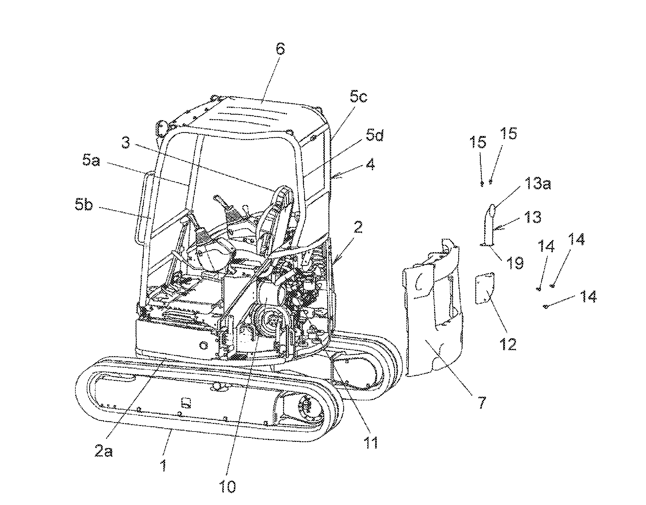
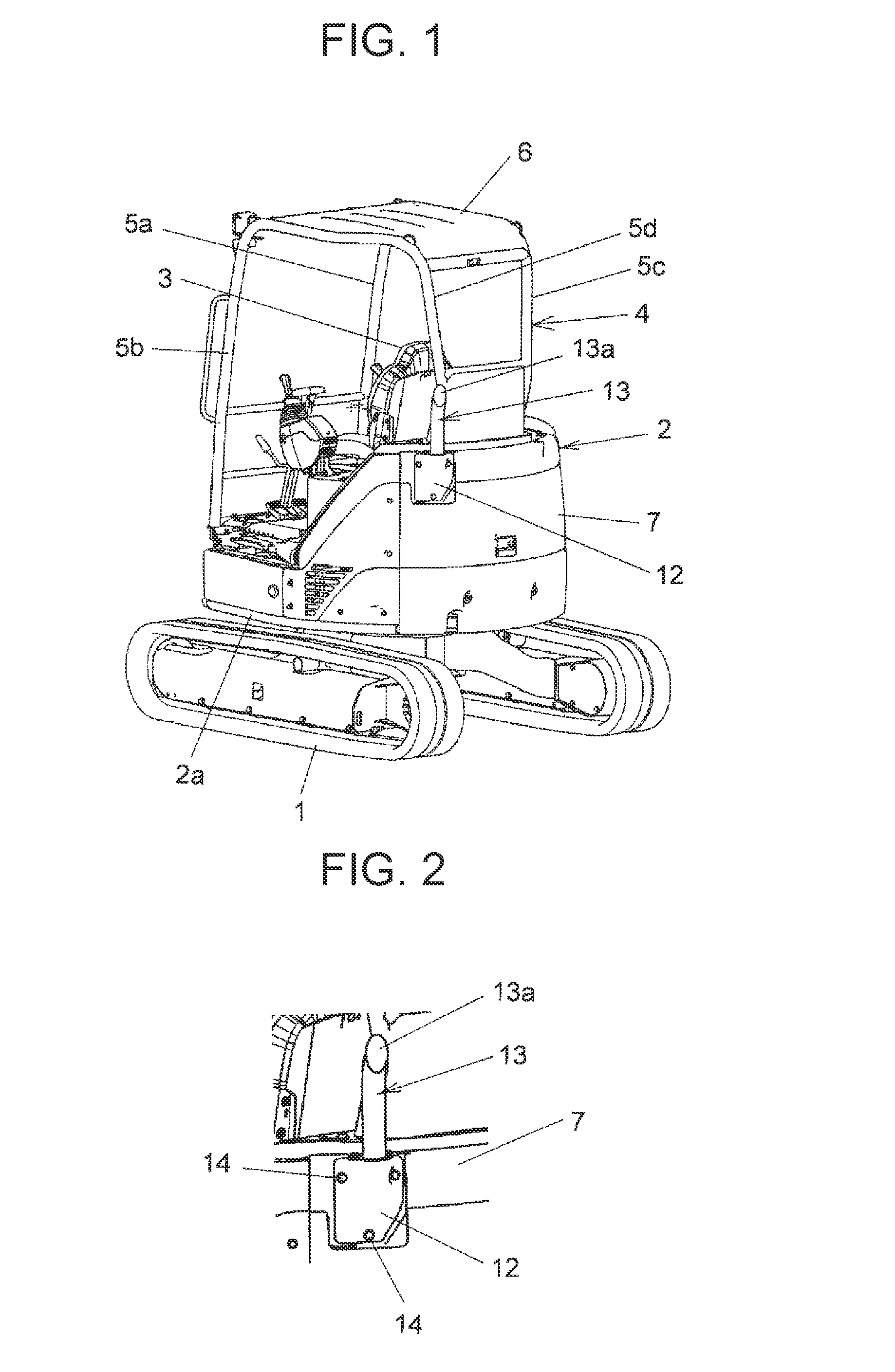
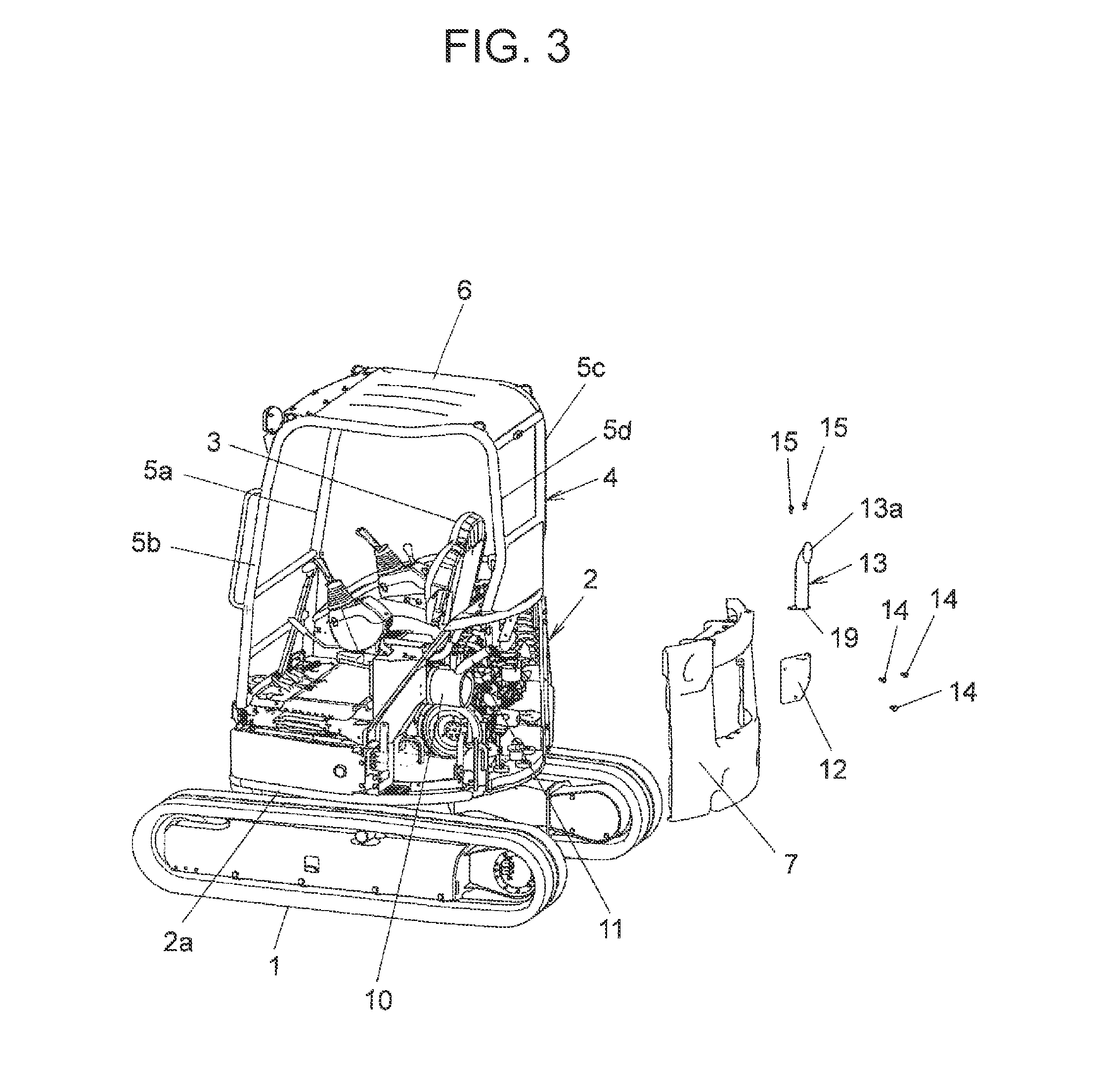
[0030]FIG. 1 is a rear three-quarter perspective view of a body of a compact excavator as the working machine according to the present invention, FIG. 2 is an enlarged fragmentary view of FIG. 1, FIG. 3 is an exploded fragmentary perspective view of FIG. 1, FIG. 4 is a side view of the body of the compact excavator shown in FIG. 1, with some parts being shown in cross-section, FIG. 5 is an enlarged fragmentary view of FIG. 4, FIG. 6 is a front three-quarter perspective view of the body of the compact excavator shown in FIG. 1, and FIG. 7 is a plan view of the body of the compact excavator shown in FIG. 1.

[0031]The compact excavator as the first embodiment is a small machine that is useful for work such as plumbing or gardening in an urban area or the like. As shown in FIGS. 1 and 4, this compact excavator is provided with a travel base 1, an upperstructure 2 disposed on the travel base 1, and unillustrated working equipment supported on a support 16 disposed at a position on a front...

second embodiment

[0042]FIG. 8 is a rear three-quarter perspective view of a body of a compact excavator as the working machine according to the present invention, FIG. 9 is a front three-quarter perspective view of the body of the compact excavator shown in FIG. 8, and FIG. 10 is a plan view of the body of the compact excavator shown in FIG. 8.

[0043]To ensure a more stable weight balance, the compact excavator shown as the second embodiment in these FIGS. 8 to 10 is provided with an extra counterweight 20 disposed such that it protrudes from the outer side wall of the counterweight 7. The exhaust pipe holding member 12 and exhaust pipe 13 are disposed such that as seen in a plan view, they do not extend outside of the extra counterweight 20. The remaining configuration is similar to that of the above-mentioned first embodiment.

[0044]The second embodiment configured as described above can bring about similar advantageous effects as the first embodiment. In addition, the exhaust pipe holding member 12...


PUM


Abstract

Provided is a working machine, which can release exhaust gas at a position above a counterweight even if no space is secured for the installation of an exhaust pipe on an upperstructure or on an upper wall of the counterweight, and which can suppress heating of the counterweight by exhaust gas. The working machine is provided with a muffler (10) into which exhaust gas is guided from an engine, and a tailpipe (11) connected to the muffler (10). Defined through a counterweight (7) is a passage (7a) in which the tailpipe (11) is inserted. The working machine is further provided with an exhaust pipe holding member (12) and an exhaust pipe (13). The exhaust pipe holding member (12) is attached to an outer side wall of the counterweight (7), and has a passage (12a) which is in communication with the passage (7a) of the counterweight (7) and in which the tailpipe (11) is inserted. The exhaust pipe (13) is disposed and held upright on the exhaust pipe holding member (12), and has a lower part, in which the tailpipe (11) is inserted, and an upper part defining therein an exhaust outlet (13a) through which the exhaust gas guided via the tailpipe (11) is released.

Description

TECHNICAL FIELD[0001]This invention relates to a working machine, such as a compact excavator, in which a passage with a tailpipe inserted therein is defined through a counterweight. The tailpipe is connected to a muffler into which exhaust gas from an engine is guided.BACKGROUND ART[0002]As a conventional technology of this type, there is one disclosed in Patent Document 1. This conventional technology has a configuration that a main muffler through which exhaust gas from an engine is guided is disposed on an upperstructure of a construction machine, an exhaust outlet portion, specifically a tailpipe is connected to the main muffler, and a passage with the tailpipe inserted therein is defined through a counterweight disposed at a lower position in a rear section of the upperstructure. Also defined in the counterweight are a cavity communicating with the above-mentioned passage and an exhaust bore for externally releasing exhaust gas guided to the cavity.[0003]According to the conve...

Claims


Application Information

Patent Timeline
Patent Type & Authority Applications(United States)
IPC IPC(8): E02F9/08E02F9/18
CPCE02F9/18E02F9/0866E02F3/325F01N13/001F01N13/082F01N2590/08
Inventor KOKURYO, OSAMUKAWAMOTO, JUNYAMIYAHARA, YASUHIRO
Owner NIHON KENKI CO LTD
Learn More