
Photovoltaic power generation system for outdoor pile rod

A technology of photovoltaic power generation system and pile pole, applied in the direction of photovoltaic power generation, photovoltaic power station, photovoltaic module, etc., can solve the problems of no power generation value, space, hardware waste, etc., and achieve the effect of low cost and simple construction

Pending Publication Date: 2020-12-08
YANGZHOU XINXIN NEW ENERGY TECH
View PDF0 Cites 0 Cited by
  • Summary
  • Abstract
  • Description
  • Claims
  • Application Information

AI Technical Summary

Problems solved by technology

Wind turbines are usually built in an open area with no shelter around them. The piles of wind turbines are exposed outdoors, which belongs to the effective lighting area, but does not directly provide power generation value for power generation, which is a waste of space and hardware.

Method used


Image

  • Photovoltaic power generation system for outdoor pile rod
  • Photovoltaic power generation system for outdoor pile rod
  • Photovoltaic power generation system for outdoor pile rod

Examples


Embodiment 1

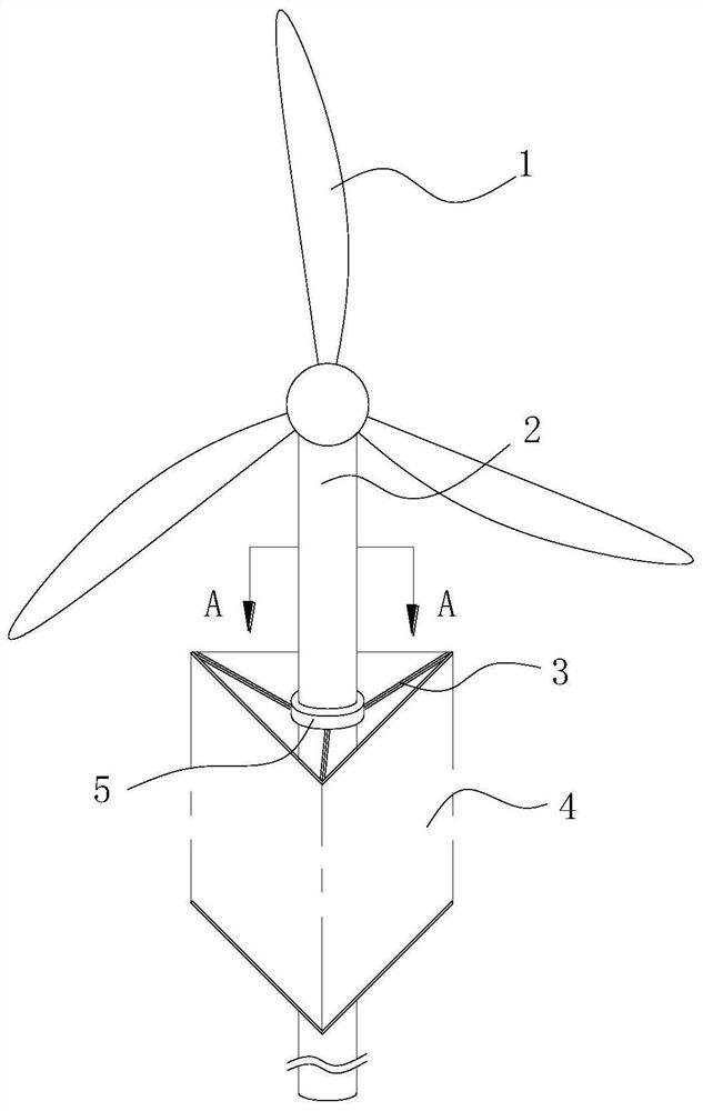
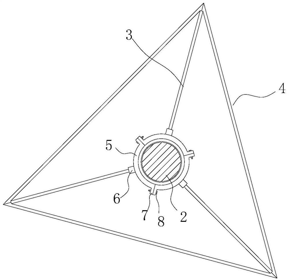
[0027] Embodiment 1: as figure 1 As shown, it can be seen in conjunction with the accompanying drawings that the present invention is designed around the pile pole 2 of the wind-driven generator without affecting the normal rotation of the wind blade 1. The photovoltaic power generation panel assembly of the present invention includes a multi-faceted photovoltaic wall 4, and the photovoltaic wall 4 is in the shape of a tall rectangular plate, and is formed by splicing one whole or multiple (usually multiple) photovoltaic panels. The photovoltaic wall 4 forms a regular polygonal tube around the pile 2 and surrounds the pile so that a closed wall structure is formed around the pile. No matter where the sunlight is, it can fully absorb the light. And the pipe body structure can also block the incoming wind from all directions, all can block it outside, the wind is easy to be drained outside the pipe body, reduce the direct impact of wind force on the pipe body, and reduce the im...

Embodiment 2

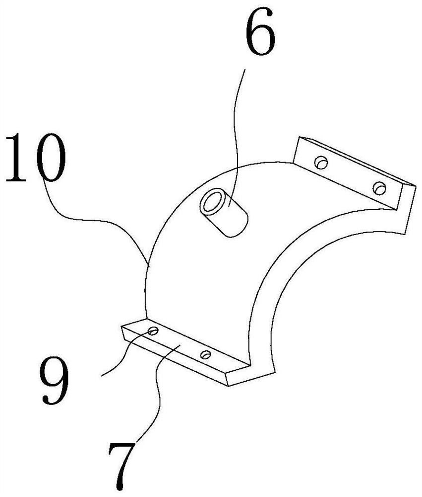
[0037] The difference between this embodiment and Embodiment 1 is that the plug has a C-shaped bayonet, and the photovoltaic wall is provided with a clamping column that matches the bayonet. The bayonet is clamped on the clamping column, and the axial direction of the clamping column is arranged horizontally. The horizontal setting of the card column can prevent the photovoltaic wall from moving up and down.

[0038] The horizontal sides of adjacent photovoltaic walls are connected by hinges. The angle can be changed arbitrarily through the hinge connection, and the effect of connection can be achieved.

[0039] Others are all the same as in Example 1.


PUM


Abstract

The invention relates to a photovoltaic power generation system for an outdoor pile rod, and the system comprises a regular polygon pipe which is formed by the sequential connection and enclosing of two horizontal sides of a plurality of flat and long rectangular photovoltaic walls with the same specification, each photovoltaic wall is formed by the splicing of a plurality of photovoltaic panels,and each included angle position of the regular polygon pipe is provided with a connecting rod. The connecting rod extends towards a pile rod of a wind driven generator, the pile rod of the wind driven generator is sleeved with an inner positioning sleeve, an outer positioning sleeve is arranged outside the positioning inner sleeve in an embracing mode, a damping bearing is arranged between the outer positioning sleeve and the inner positioning sleeve, and the connecting rod is fixedly connected with the outer positioning sleeve. The system is directly modified and additionally arranged in anexisting wind driven generator, the construction is easy, an electricity storage system of the wind driven generator is shared by an electricity storage system, the cost is low, the light energy utilization rate is increased, and in order to adapt to the windy environment, the regular polygon pipe can rotate.

Description

technical field [0001] The invention relates to a photovoltaic power generation system for outdoor piles, belonging to the technical field of photovoltaic power generation applications. Background technique [0002] A wind turbine is a mechanical power generation device built in an outdoor area with stable wind. It generates electricity through the rotation of the wind blades, converts mechanical energy into electrical energy, and can store the electrical energy. Wind turbines are usually built in an open area with no shelter around them. The wind turbine piles are exposed outdoors, which is an effective lighting area, but it does not directly provide power generation value for power generation, which is a waste of space and hardware. Contents of the invention [0003] In order to solve the above technical problems, the present invention provides a photovoltaic power generation system for outdoor piles, and its specific technical scheme is as follows: [0004] A photovolt...

Claims


Application Information

Patent Timeline
IPC IPC(8): H02S10/12H02S20/30H02S10/20F03D9/00F03D9/11
CPCH02S10/12H02S20/30H02S10/20F03D9/007F03D9/11Y02E10/50Y02E10/72Y02E70/30
Inventor 陈宝山
Owner YANGZHOU XINXIN NEW ENERGY TECH
Learn More