Video endoscope

a technology of endoscope and video, which is applied in the field of video endoscope, can solve problems such as affecting the optical quality of the system

Inactive Publication Date: 2015-03-05
OLYMPUS WINTER & IBE
View PDF5 Cites 13 Cited by
  • Summary
  • Abstract
  • Description
  • Claims
  • Application Information

AI Technical Summary

Benefits of technology

[0014]An object is to provide a surgical instrument, such as video endoscopes, with a stable arrangement of an optical transmitting device for transmitting image data from the hermetically encapsulated housing, wherein the effort and the installation should be as minimal as possible.

Problems solved by technology

In the case of optical endoscopes and in particular video endoscopes, it is necessary to protect the optical components and the image sensor from steam which otherwise condenses on the lens system upon cooling and can impair the optical quality of the system.

Method used


Image

  • Video endoscope
  • Video endoscope
  • Video endoscope

Examples


Embodiment Construction

[0036]In the drawings, the same or similar types of elements and / or parts are provided with the same reference numbers so that a re-introduction is omitted.

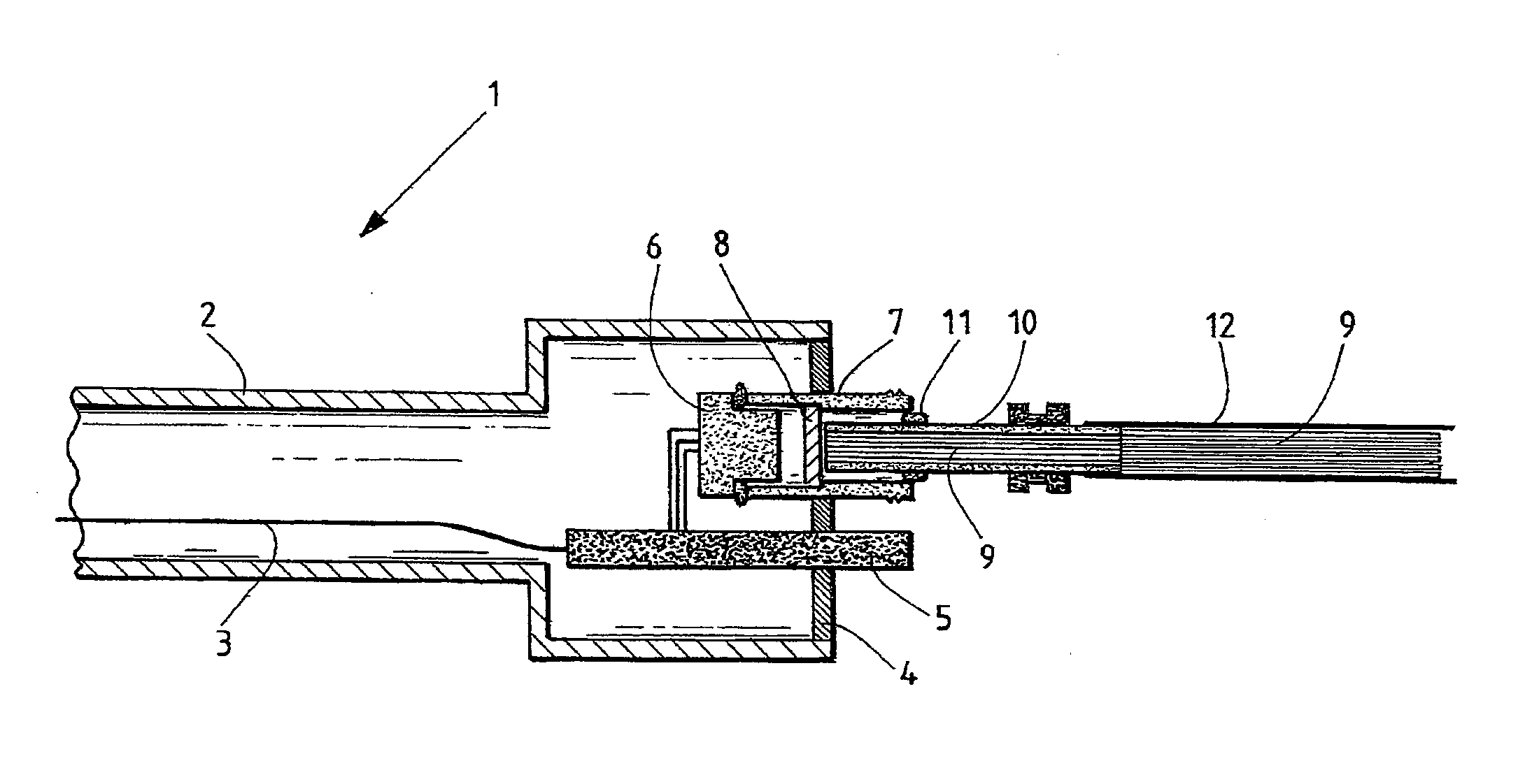
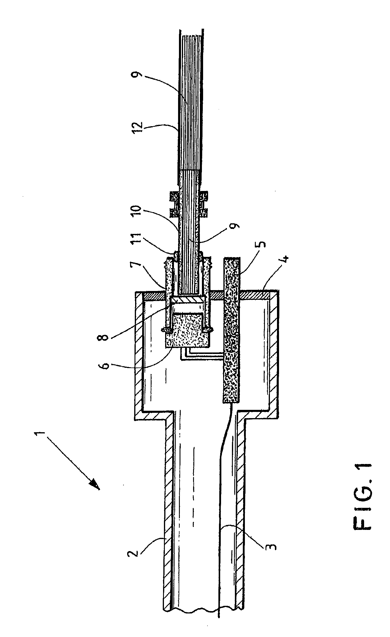
[0037]FIG. 1 shows schematically in cross-section a proximal end region of a video endoscope 1 shown schematically. The video endoscope 1 has an endoscope shaft 2 elongated as a housing, on the distal end of which a window is provided, wherein a video camera is arranged as an optical image sensor unit behind the window in the endoscope shaft. In order to transmit the image data of the video camera, an image data line 3 is provided in the endoscope shaft 2 in order transmit the image data of the video camera.

[0038]An end plate 4, e.g. made of glass, is arranged in the shown proximal end region of the endoscope shaft 2, in order to close the proximal end face of the endoscope shaft 2. A through-contact device 5 designed as a rigid HTCC conductor plate is arranged in the end plate 4 in order to provide electrical power for the units...


PUM


Abstract

A video endoscope including: an elongated housing; an image sensor unit arranged in the elongated housing; an optical transmitting unit arranged in the elongated housing and connected to the image sensor unit; and a through contact device, wherein the optical transmitting unit is arranged at a proximal end of the elongated housing on the through-contact device, the through-contact device penetrates through a wall of the elongated housing and the through-contact device is arranged such that it is mounted in a hermetically sealed manner in the wall of the elongated housing.

Description

CROSS-REFERENCE TO RELATED APPLICATION[0001]The present application is a continuation of PCT / EP2013 / 001368 filed on May 8, 2013, which is based upon and claims the benefit to DE 10 2012 208 358.8 filed on May 18, 2012, the entire contents of each of which are incorporated herein by reference.BACKGROUND[0002]1. Field[0003]The present application relates to a video endoscope comprising an elongated, preferably hermetically sealed, housing for accommodating an image sensor unit, more particularly video camera, preferably arranged in the distal region of the housing, wherein an optical transmitting unit connected to the image sensor unit is arranged in the housing.[0004]2. Prior Art[0005]Video endoscopes are designed elongated with a small cross-section. In generic video endoscopes, image sensors and the upstream optical systems are normally arranged in the distal region of the endoscope shaft, that is, in the region of the endoscope tip. Image signals and control signals are transmitte...

Claims


Application Information

Patent Timeline
Patent Type & Authority Applications(United States)
IPC IPC(8): A61B1/00A61B1/05
CPCA61B1/00126A61B1/051A61B1/00165A61B1/00142A61B1/00124A61B1/053A61B1/00096A61B1/0011A61B1/00013A61B1/05
Inventor JUNGBAUER, SEBASTIANSCHERR, PATRICKSTUEHLE, SEBASTIANPABST, SVEN
Owner OLYMPUS WINTER & IBE
Why Eureka
Try Eureka