Synthesis and annealing of manganese bismuth nanoparticles

a technology of manganese bismuth and nanoparticles, which is applied in the direction of magnetic materials, magnetic bodies, transportation and packaging, etc., can solve the problem of unstable supply of manganese bismuth nanoparticles

Active Publication Date: 2015-03-12
TOYOTA JIDOSHA KK
View PDF2 Cites 28 Cited by
  • Summary
  • Abstract
  • Description
  • Claims
  • Application Information

AI Technical Summary

Benefits of technology

[0052]The as-synthesized MnBi nanoparticles were demonstrated on a very weak coercivity (<100 Oe). Samples of the nanoparticles were annealed in situ with aVSM oven attachment. It was initially found that annealing the nanoparticles at 600 K, in a 3 T field, produced improvement to both the magnetic saturation (Ms) and coercivity (Hc). Additionally, Mr / Ms improved with this annealing protocol. Hc values up to 1 T were measured, with an Mr / Ms ratio of 45% (FIG. 3).
[0053]Investigation at lower annealing temperature (550 K) showed that a similar 1 T Hc could be reached, but that it required over 40 hrs of annealing, as opposed to ˜11 hrs at 600 K (FIG. 4). Annealing the same batch of MnBi nanoparticles at 650 K gave very poor results, with a maximum Hc of only approximately 500 Oe.

Problems solved by technology

However, because this material is based on the rare earth element neodymium, it is expensive and often the available supply is not stable.

Method used


Image

  • Synthesis and annealing of manganese bismuth nanoparticles
  • Synthesis and annealing of manganese bismuth nanoparticles
  • Synthesis and annealing of manganese bismuth nanoparticles

Examples


example 1

MnBi Nanoparticle Synthesis

[0049]200 mL of THF, 0.371 g Mn powder and 11.5 mL of 2 M LiBH4 / THF solution are combined. The reaction was first stirred at 23° C. for 24 hrs and then at 60° C. for an additional 24 hrs. To the resulting mixture was added a solution of 4.413 g bismuth neodecanoate dissolved in 200 mL THF. The bismuth neodecanoate solution was added slowly over 20 mins to the stirring Mn / LiBH4 solution. After the bismuth neodecanoate addition was complete, 0.513 g octylamine were added to the product solution. The nanoparticles aggregated over the following 5 mins and were washed with water to remove reaction side products.

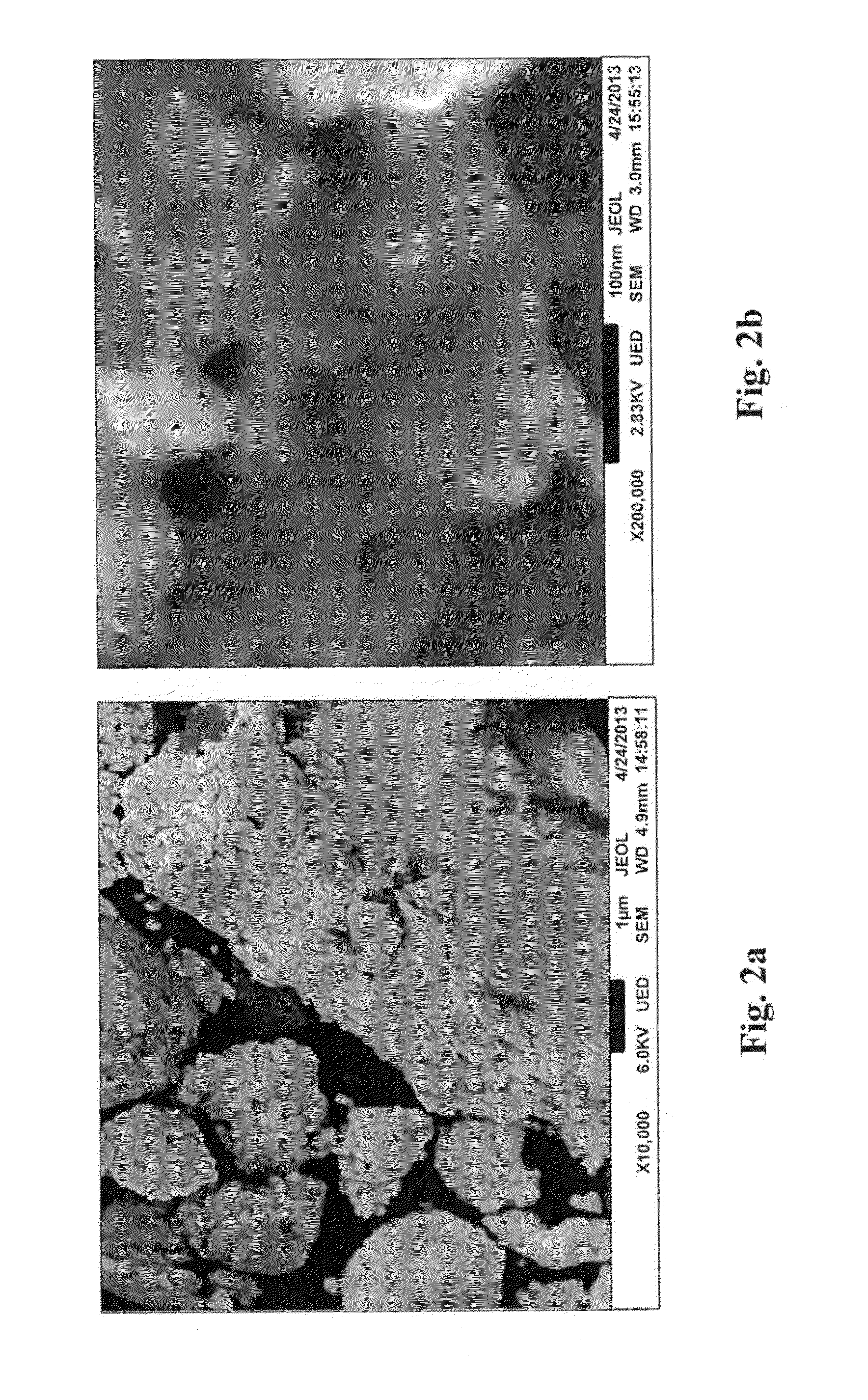
Characterization of the MnBi Nanoparticles
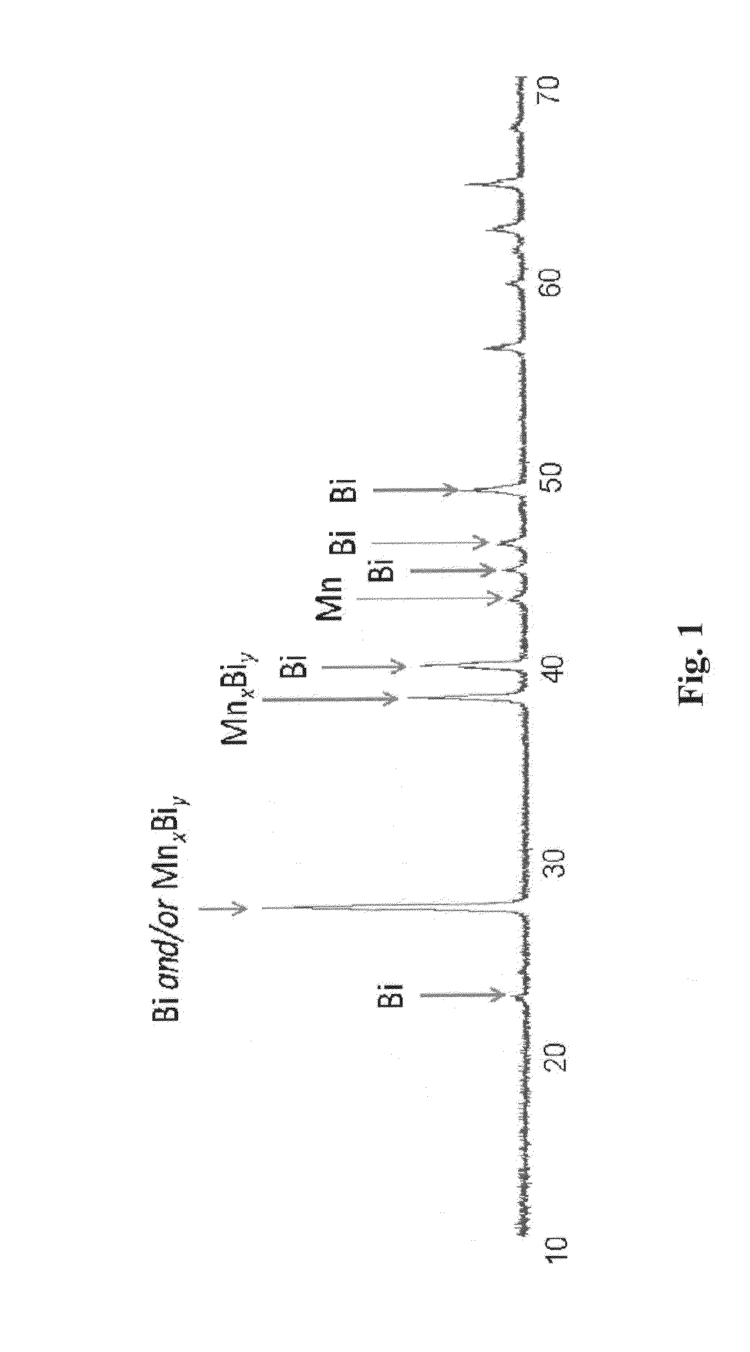
XRD Analysis

[0050]The XRD spectrum of the MnBi nanoparticles indicated the presence of three different crystalline materials present in the sample: MnBi alloy, Mn metal, and Bi metal (see FIG. 1). The MnBi nanoparticles were calculated to be approximately 30 nm in diameter based on peak width in this XRD spectrum...

example 2

Annealing Effects on MnBi Nanoparticles

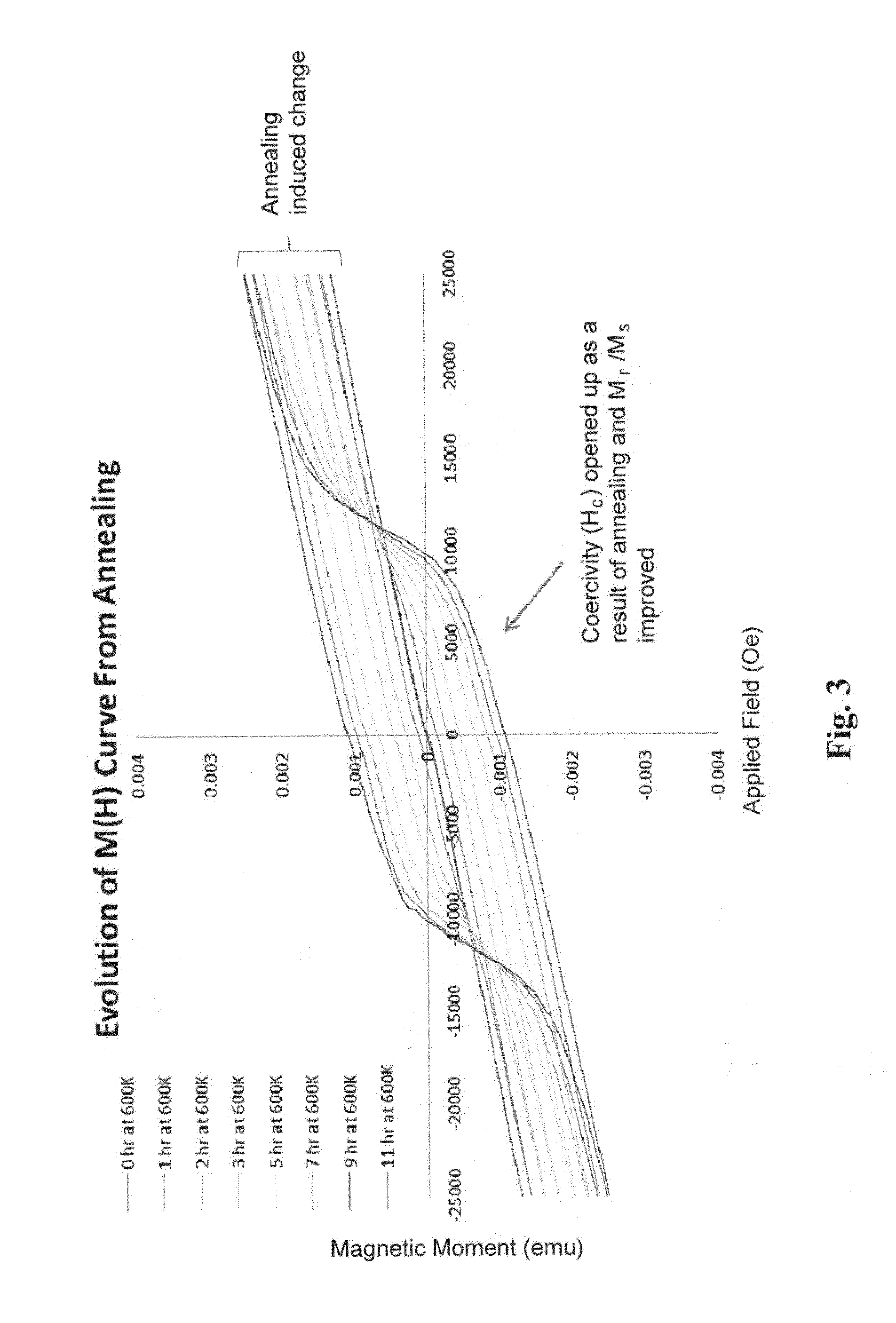
[0052]The as-synthesized MnBi nanoparticles were demonstrated on a very weak coercivity (s) and coercivity (Hc). Additionally, Mr / Ms improved with this annealing protocol. Hc values up to 1 T were measured, with an Mr / Ms ratio of 45% (FIG. 3).

[0053]Investigation at lower annealing temperature (550 K) showed that a similar 1 T Hc could be reached, but that it required over 40 hrs of annealing, as opposed to ˜11 hrs at 600 K (FIG. 4). Annealing the same batch of MnBi nanoparticles at 650 K gave very poor results, with a maximum Hc of only approximately 500 Oe.

[0054]Ferromagnetic MnBi only exists in what is referred to as the ‘low temperature phase’ region of the MnBi phase diagram (FIG. 5a). Above it exists what is referred to as the ‘high temperature phase’. The high temperature phase is known to exhibit antiferromagnetic behavior. A sample of MnBi nanoparticles was heated to 800 K to induce this change from the ferromagnetic low temperature pha...


PUM

PropertyMeasurementUnit
particle sizeaaaaaaaaaa
grain sizeaaaaaaaaaa
particle diameteraaaaaaaaaa

Abstract

The claimed invention provides a wet chemical method to prepare manganese bismuth nanoparticles having a particle diameter of 5 to 200 nm. When annealed at 550 to 600K in a field of 0 to 3T the nanoparticles exhibit a coercivity of approximately 1T and are suitable for utility as a permanent magnet material. A permanent magnet containing the annealed MnBi nanoparticles is also provided.

Description

BACKGROUND OF THE INVENTION[0001]This invention is related to the synthesis and preparation of novel materials for use as strong permanent hard magnets. Many of today's advancing technologies require an efficient and strong hard magnet as a basic component of the device structure. Such devices range from cellular phones to high performance electric motors and significant effort is ongoing throughout the industry to find materials which not only meet current requirements, but also ever increasing demand for efficient, less expensive and easily produced hard magnet materials.[0002]Conventionally, neodymium iron borate is generally recognized as one of the strongest, best performing hard magnet materials available. However, because this material is based on the rare earth element neodymium, it is expensive and often the available supply is not stable. Accordingly, there is a need for a material which performs equally or better than neodymium iron borate as a hard magnet but which is ba...

Claims


Application Information

Patent Timeline
Patent Type & Authority Applications(United States)
IPC IPC(8): H01F1/047B22F1/00H01F1/06B22F9/20B22F1/054B22F1/142
CPCH01F1/047B22F9/20B22F1/0003B22F2304/056H01F1/065B22F2202/05B22F2304/054H01F1/06C22C12/00C22C22/00C22C2202/02H01F1/0045B22F1/054B22F1/142
Inventor ROWE, MICHAEL PAUL
Owner TOYOTA JIDOSHA KK
Why Eureka
Try Eureka