
Vehicles and methods for magnetically managing legs of rail-based photovoltaic modules during installation

a photovoltaic module and magnetic management technology, applied in the direction of heat collector mounting/support, lighting and heating equipment, hoisting equipment, etc., can solve the problems of uneven terrain, difficult installation of photovoltaic arrays, and extensive grading and earth moving

Inactive Publication Date: 2015-03-12
ALION
View PDF12 Cites 12 Cited by
  • Summary
  • Abstract
  • Description
  • Claims
  • Application Information

AI Technical Summary

Benefits of technology

The present invention provides a method and vehicle for installing photovoltaic modules with support legs. The invention involves using a magnetic field to manage the support legs during installation, allowing for easier handling and positioning of the modules. This improves efficiency and accuracy in the installation process, and reduces the risk of damage or injury during installation. The invention can be applied to various types of photovoltaic modules and has a wide range of benefits and applications.

Problems solved by technology

The installation of photovoltaic arrays often presents logistical challenges.
Not only does the site for the photovoltaic array need to be properly prepared, but large quantities of materials also need to be transported to and within the site.
For example, the site for the photovoltaic array may have existing vegetation that would interfere with the installation and operation of the photovoltaic array.
The site may also have uneven terrain that usually requires extensive grading and earth moving.
Each of these operations can be time-consuming and expensive.

Method used


Image

  • Vehicles and methods for magnetically managing legs of rail-based photovoltaic modules during installation
  • Vehicles and methods for magnetically managing legs of rail-based photovoltaic modules during installation
  • Vehicles and methods for magnetically managing legs of rail-based photovoltaic modules during installation

Examples


Embodiment Construction

[0015]The present invention is directed to installation of photovoltaic modules in certain embodiments. More particularly, certain embodiments of the invention provide vehicles and methods for managing legs of photovoltaic modules during installation. Merely by way of example, the invention has been applied to magnetically managing legs of rail-based photovoltaic modules during installation. But it would be recognized that the invention has a much broader range of applicability.

[0016]Illustratively, the present vehicles and methods can be used for installing rail-based arrays of photovoltaic modules. Such arrays can, in some embodiments, include an elongated rail including first and second support surfaces and at least one mounting surface disposed between the first and second support surfaces. An array of the photovoltaic modules can be coupled to the first mounting surface and raised relative to the first and second support surfaces in a manner such as provided herein. Optionally,...


PUM


Abstract

An exemplary method for installing at an installation site a photovoltaic module including a panel and support legs includes disposing the photovoltaic module over a support surface such that the support legs are in a stowed position; lifting the photovoltaic module from a support surface while engaging a magnetic field with the support legs so as to maintain the support legs in the stowed position; disengaging the magnetic field from the support legs of the lifted photovoltaic module so as to release the support legs from the stowed position to an installation position in which the support legs are rotated downwards relative to the stowed position; and lowering the photovoltaic module to the installation site with the support legs in the installation position so as to install the photovoltaic module at the installation site, the support legs supporting the panel at the installation site.

Description

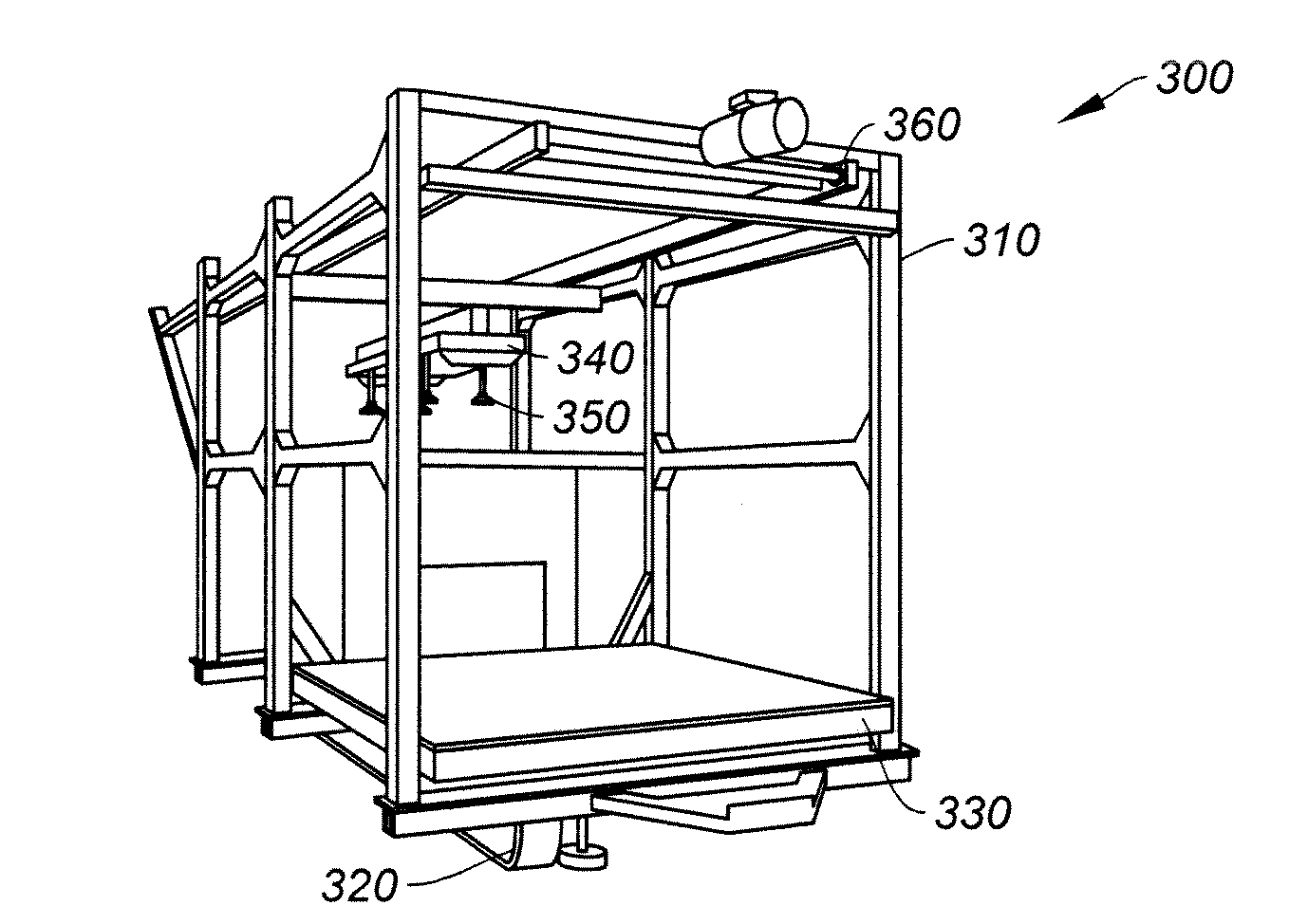
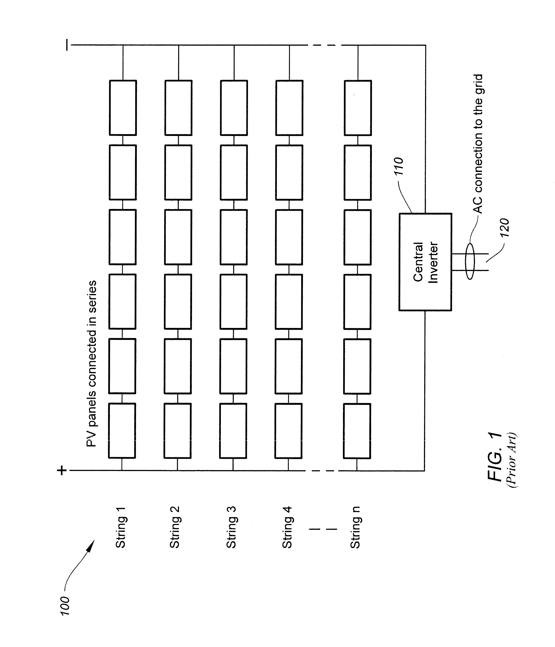
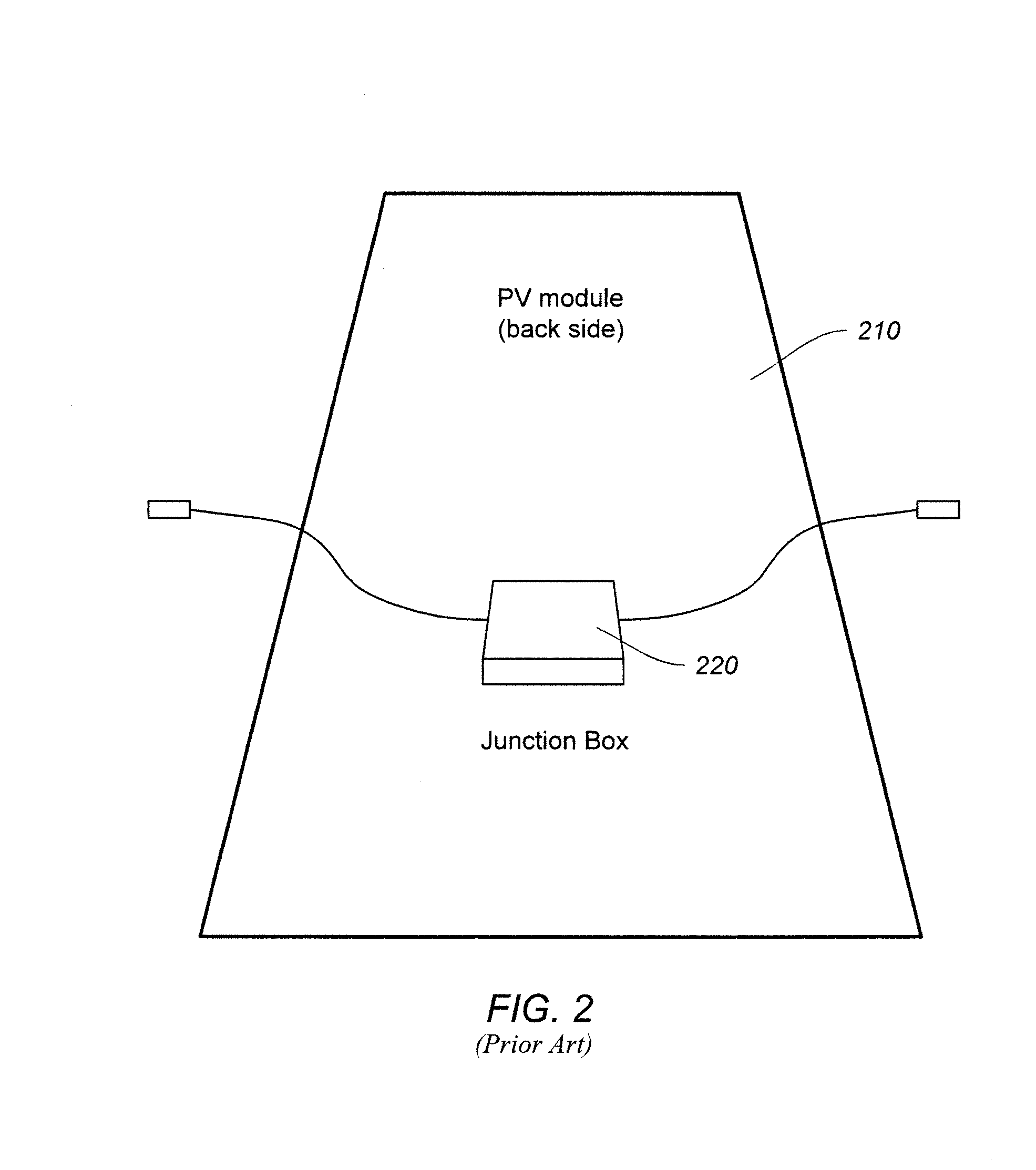
CROSS-REFERENCE TO RELATED APPLICATIONS[0001]This application claims priority to U.S. Provisional Patent Application No. 61 / 876,666, filed on Sep. 11, 2013, the entire contents of which are incorporated by reference herein.BACKGROUND OF THE INVENTION[0002]The present invention is directed to installation of photovoltaic modules according to some embodiments. More particularly, certain embodiments of the invention provide vehicles and methods for managing legs of photovoltaic modules during installation. Merely by way of example, the invention has been applied to magnetically managing legs of rail-based photovoltaic modules during installation. But it would be recognized that the invention has a much broader range of applicability.[0003]Photovoltaics convert sunlight into electricity, providing a desirable source of clean energy. FIG. 1 is a simplified diagram of a conventional photovoltaic array. The photovoltaic array 100 includes strings 1, 2, 3, 4, . . . n, where n is a positive ...

Claims


Application Information

Patent Timeline
IPC IPC(8): B66C19/00B66C1/02B66C1/06
CPCB66C19/00B66C1/02B66C1/06H02S20/00H02S40/00Y02E10/50Y02E10/47F24S25/10F24S2025/014B60P1/5423B61D47/00
Inventor FRENCH, ADAMWHEELER, TIMOTHYHENNESSY, KEVINCROWE, JESSCASTRO HERNANDEZ, LUIS FRANCISCO
Owner ALION
Learn More