

Imaging lens
a technology of imaging lens and image sensor, which is applied in the field of imaging lens, can solve the problems of difficult to provide imaging lens, difficult to correct various aberrations, and inability to maintain the high optical performance achieved so far with a conventionally smaller image sensor, and achieve the effect of higher optical performan
- Summary
- Abstract
- Description
- Claims
- Application Information
AI Technical Summary
Benefits of technology
Problems solved by technology
Method used
Image

Examples
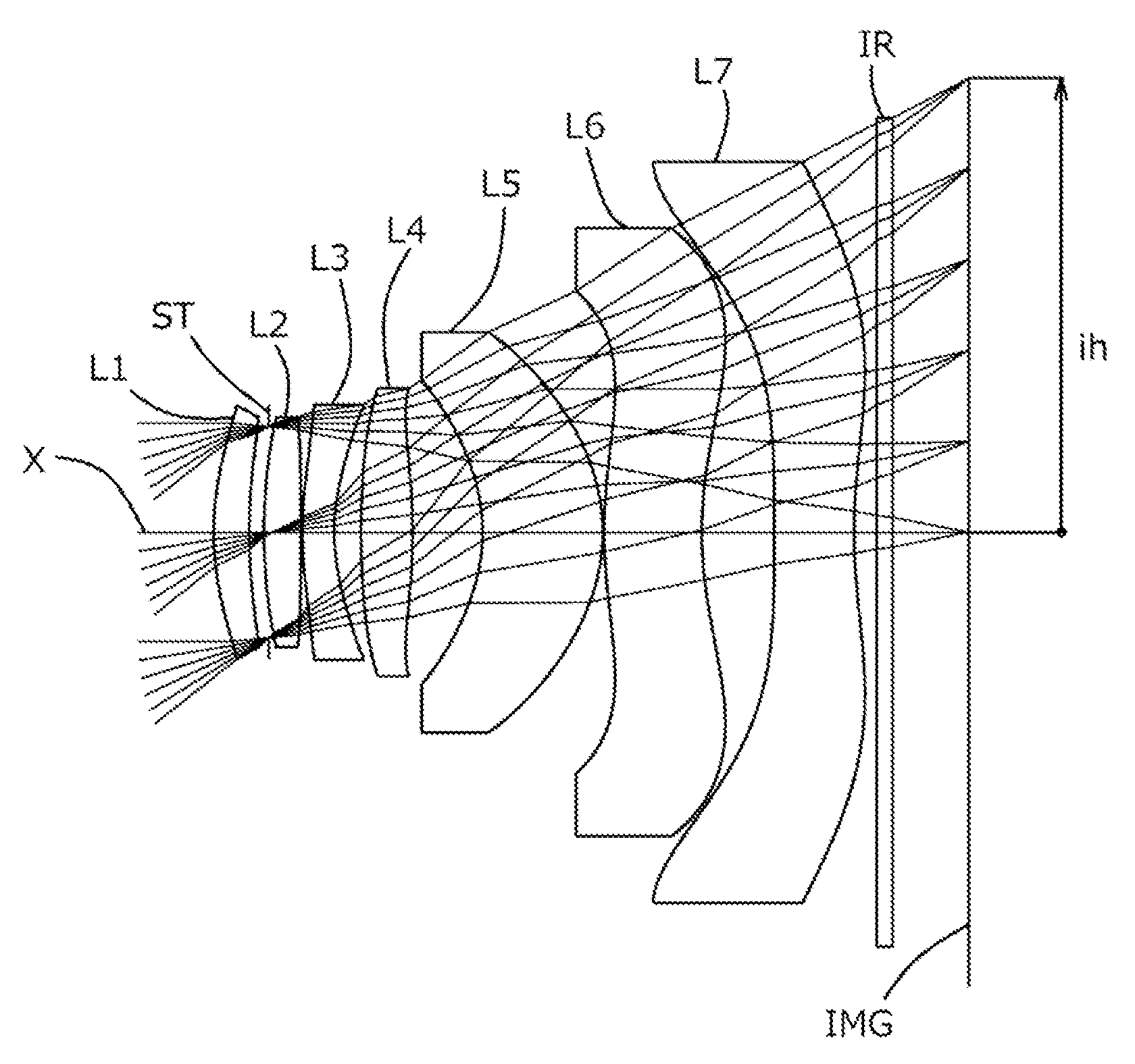
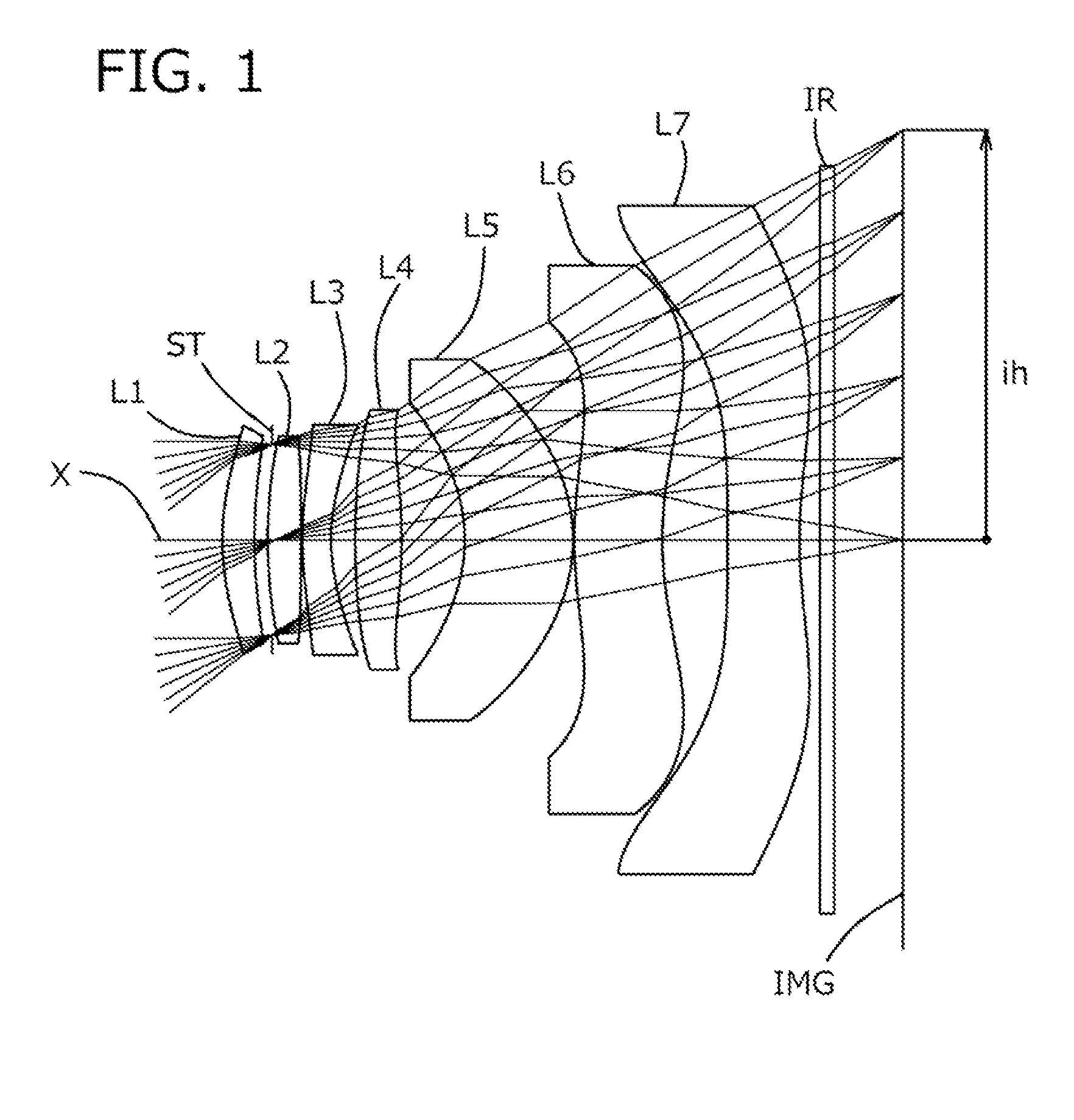
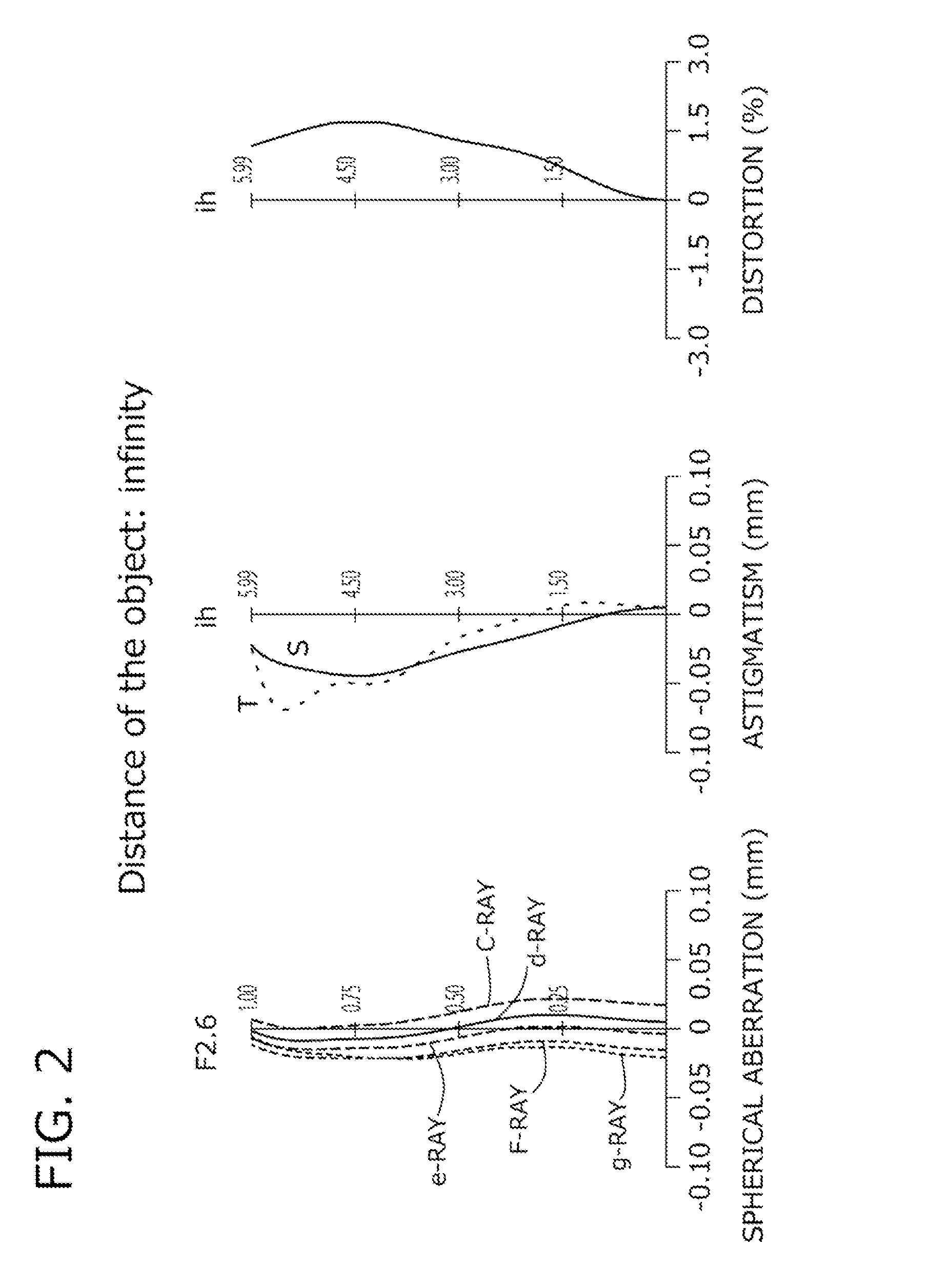
example 1
[0120]The basic lens data of Example 1 is shown below in Table 1.
TABLE 1Example 1in mmf = 7.51Fno = 2.6ω (°) = 38.2ih = 5.99TTL = 9.88Surface DataCurvatureSurfaceRefractiveAbbeSurface No. iRadius rDistance dIndex NdNumber vd(Object Surface)InfinityInfinity 1*3.9240.4681.543855.57 2*7.2510.256 3 (Stop)Infinity−0.060 4*8.0100.4851.543855.57 5*−48.2810.018 6*4.6410.4221.634923.97 7*2.6520.353 8*11.6350.6801.543855.57 9*−7.5960.92110*−2.3981.5841.543855.5711*−2.5150.01912*6.4011.2871.543855.5713*5.1130.95514*−85.81411.0511.614225.5815*6.98620.30016Infinity0.2101.516864.2017Infinity0.985Image PlaneInfinityConstituent Lens DataLensStart SurfaceFocal Length1114.982412.6736−10.62488.5651025.17612−72.11714−10.47LensComposite Focal LengthFirst Lens-Second Lens7.09Fourth Lens-Fifth Lens7.96Sixth Lens-Seventh Lens−9.56Aspheric Surface Data1st Surface2nd Surface4th Surface5th Surface6th Surface7th Surface8th Surfacek0.000E+000.000E+000.000E+000.000E+00−2.298E+01−6.498E+000.000E+00A4−3.681E−03−5....
example 2
[0124]The basic lens data of Example 2 is shown below in Table 2.
TABLE 2Example 2in mmf = 7.47Fno = 2.6ω (°) = 38.3ih = 5.99TTL = 9.65Surface DataCurvatureSurfaceRefractiveAbbeSurface No. iRadius rDistance dIndex NdNumber vd(Object Surface)InfinityInfinity 1*3.7120.481.54381255.5699 2*6.5600.280 3 (Stop)Infinity−0.080 4*8.6760.5101.543855.57 5*−28.5370.029 6*5.9440.5641.634923.97 7*3.0450.343 8*12.7940.6811.543855.57 9*−7.9840.99810*−2.3921.1861.543855.5711*−2.3860.02112*7.7691.4761.543855.5713*5.1470.86414*−62.2881.1051.614225.5815*7.4970.29516Infinity0.2101.516864.2017Infinity0.750Image PlaneInfinityConstituent Lens DataLensStart SurfaceFocal Length1114.842412.2936−10.63489.1551024.78612−34.98714−10.83LensComposite Focal LengthFirst Lens-Second Lens6.97Fourth Lens-Fifth Lens7.98Sixth Lens-Seventh Lens−8.43Aspheric Surface Data1st Surface2nd Surface4th Surface5th Surface6th Surface7th Surface8th Surfacek0.000E+000.000E+000.000E+000.000E+00−2.947E+01−6.483E+000.000E+00A4−5.802E−03−7...
example 3
[0128]The basic lens data of Example 3 is shown below in Table 3.
TABLE 3Example 3in mmf = 7.51Fno = 2.6ω (°) = 37.7ih = 5.99TTL = 9.93Surface DataCurvatureSurfaceRefractiveAbbeSurface No. iRadius rDistance dIndex NdNumber vd(Object Surface)InfinityInfinity 1*4.1350.4681.543855.57 2*8.0810.237 3 (Stop)Infinity0.000 4*9.4820.5041.543855.57 5*−22.4820.018 6*5.2400.5311.634923.97 7*2.8050.385 8*13.5320.5771.543855.57 9*−8.3070.93110*−2.4991.5251.543855.5711*−2.5020.02012*5.8291.2561.543855.5713*4.6860.85214*42.98851.0031.614225.5815*6.0760.30016Infinity0.2101.516864.2017Infinity1.175Image PlaneInfinityConstituent Lens DataLensStart SurfaceFocal Length1114.942412.3336−10.38489.5551021.52612−71.69714−11.64LensComposite Focal LengthFirst Lens-Second Lens7.00Fourth Lens-Fifth Lens8.10Sixth Lens-Seventh Lens−10.50Aspheric Surface Data1st Surface2nd Surface4th Surface5th Surface6th Surface7th Surface8th Surfacek0.000E+000.000E+000.000E+000.000E+00−2.524E+01−6.329E+000.000E+00A4−4.543E−03−5.87...
PUM
 Abstract
Description
Claims
Application Information