Puncture device and puncture apparatus

Active Publication Date: 2015-03-12
TERUMO KK
View PDF5 Cites 8 Cited by
  • Summary
  • Abstract
  • Description
  • Claims
  • Application Information

AI Technical Summary

Benefits of technology

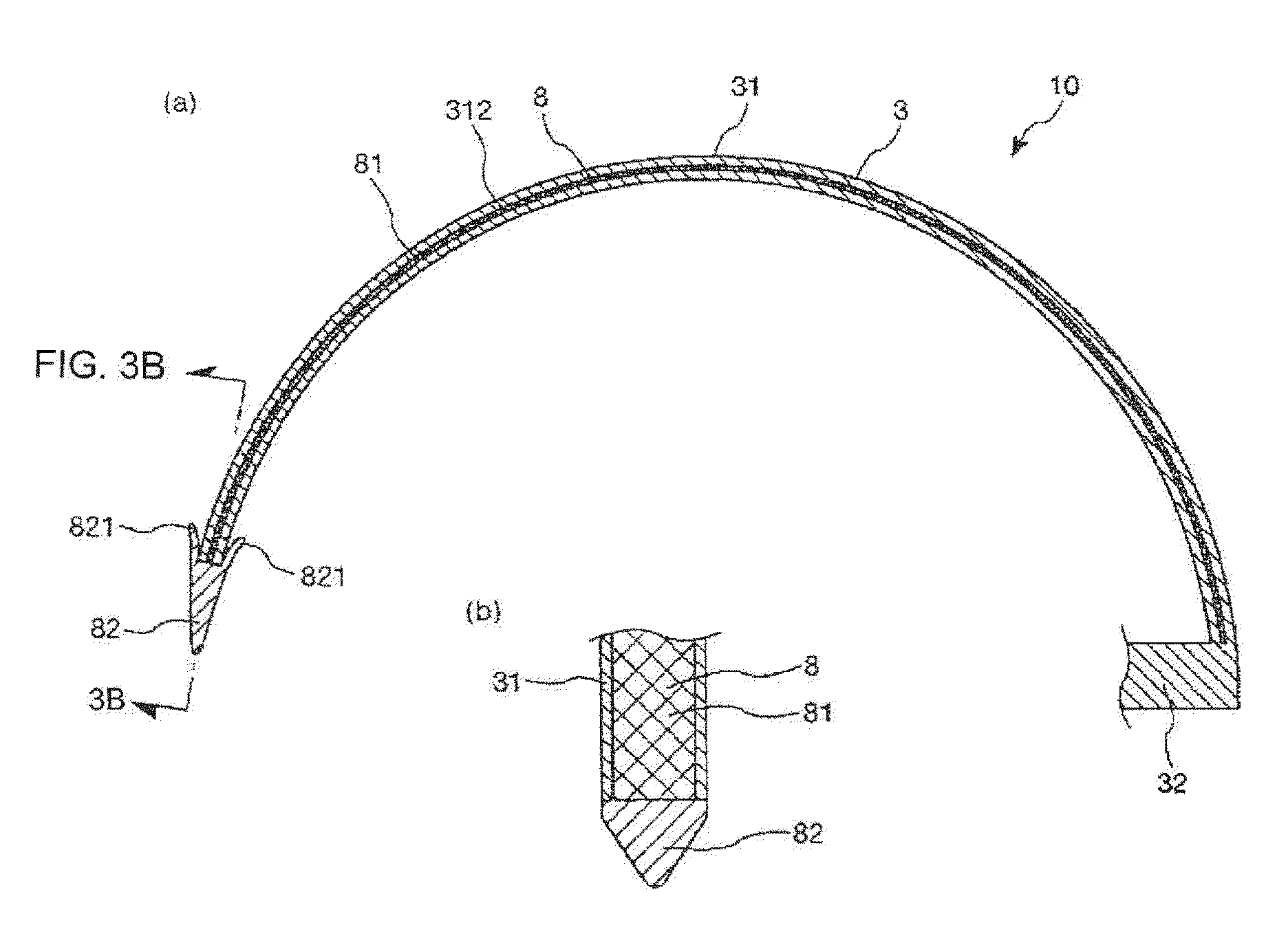
[0006]In accordance with an exemplary embodiment, a puncture device and a puncture apparatus are disclosed, by which a biological tissue supporting implant can be buried int

Problems solved by technology

However, if the vagina is incised once, a situation may occur that the sling is exposed to the inside of the vagina from a wound caused by the incision of the vagina, and complications may be caused by an infection from the wound or the like.
Further, since the vagina is incise

Method used


Image

  • Puncture device and puncture apparatus
  • Puncture device and puncture apparatus
  • Puncture device and puncture apparatus

Examples


second embodiment

[0109]As depicted in FIGS. 10 to 12, in the puncture apparatus 1 of the second embodiment, the biological tissue supporting implant 81a of the implant assembly 8 can include an implant (or indwelling article) main body 810, a proximal end of a string (first string member) 83, which is connected to the distal end of the implant main body 810, a distal end of a string (second string member) 84, which is connected to the proximal end of the implant main body 810, and a holding member 85, which is connected to the proximal end of the string 84. For example, the string 83 can be fixed at a proximal end portion of string 83 to a distal end portion of the implant main body 810, and the string 84 can be fixed at a distal end portion of string 84 to a proximal end portion of the implant main body 810. Further, the holding member 85 can be fixed to a proximal end portion of string 84 and is held removably, for example, detachably, on the hollow portion 312 at a proximal end portion of the pun...

first embodiment

[0125]With the present puncture apparatus 1, similar effects to those by the first embodiment described hereinabove are achieved.

[0126]In accordance with an exemplary embodiment, while the needle tip portion in the present exemplary embodiment is fixed to a distal end portion of a string, the fixation of the needle tip portion is not limited to this, and the needle tip portion may be held removably, for example, detachably, on a string.

third embodiment

[0127]FIG. 20 is a cross sectional view depicting a puncture device according to the puncture apparatus of the present disclosure.

[0128]In the following, the third embodiment is described principally in regard to differences from the second exemplary embodiment described hereinabove, while the description of similar items is omitted.

[0129]As depicted in FIG. 20, in the puncture apparatus 1 of the third exemplary embodiment, the puncture needle 31 of the puncture device 10 has a needle tip portion 35 at a distal end portion of the puncture needle 31. In accordance with an exemplary embodiment, the needle tip portion 35 can be fixed to or integrated with the distal end portion of the puncture needle 31. Further, the needle tip portion 35 has a sharp needle tip at the distal end of the needled tip portion 35. Further, the hollow portion 312 can be open at both of the distal end and the proximal end of the puncture needle 31. Further, the puncture device 10 has a pusher not depicted for...


PUM


Abstract

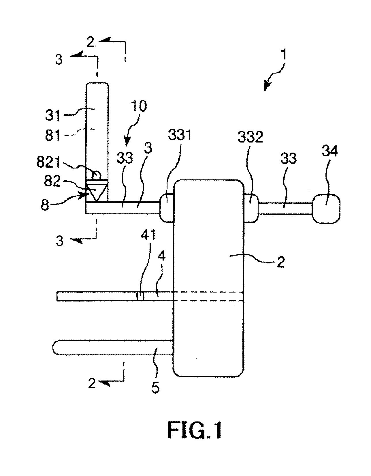
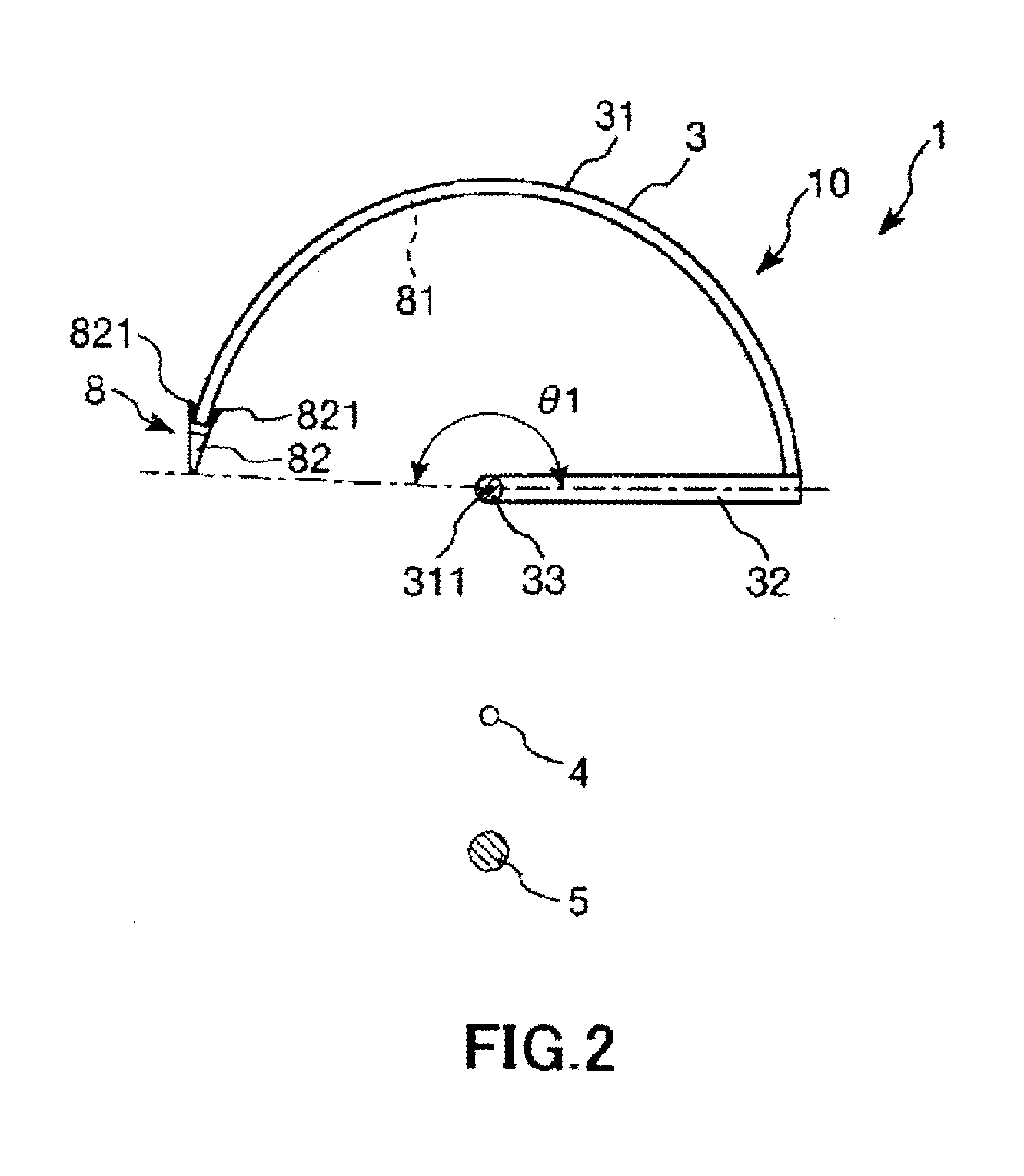
A puncture device, a puncture apparatus, and a method are disclosed, the puncture apparatus including a puncture device for puncturing a biological tissue, a urethral-insertion member, a vaginal insertion member, and a supporting member which supports the urethral-insertion member, vaginal insertion member and a puncture member of the puncture device. The puncture device includes a puncture needle for puncturing a biological tissue, a shaft portion and a connection portion for connecting the puncture needle and the shaft portion to each other, and an implant assembly positioned at a distal end of the puncture needle and having a needle tip portion for puncturing a biological tissue and a biological tissue supporting implant. The puncture needle has a form of a pipe and has a tubular portion. The biological tissue supporting implant is accommodated in the hollow portion.

Description

CROSS-REFERENCES TO RELATED APPLICATIONS[0001]This application is a continuation of International Application No. PCT / JP2013 / 056681 filed on Mar. 11, 2013, and claims priority to Japanese Application No. 2012-079036 filed on Mar. 30, 2012, the entire content of both of which is incorporated herein by reference.TECHNICAL FIELD[0002]The present disclosure relates to a puncture device and a puncture apparatus.BACKGROUND DISCUSSION[0003]If a person suffers from a urinary incontinence, for example, if a person suffers from a stress urinary incontinence, then urine leakage can be caused by application of abdominal pressure during a normal exercise or by laughing, coughing, sneezing and the like. The cause of this may be, for example, that the pelvic floor muscle which is a muscle for supporting the urethra is loosened by birth or the like.[0004]For the treatment of urinary incontinence, a surgical treatment is effective, in which there is used, for example, a belt-shaped biological tissue...

Claims


Application Information

Patent Timeline
IPC IPC(8): A61B17/34A61F2/00
CPCA61B17/3468A61F2/0045A61F2/0063A61B2017/3409A61F2002/0072A61B2017/3407A61B17/3403A61B17/0482A61B17/0491A61B17/42A61B2017/061A61B2017/00805A61B17/0469A61B2017/0608
Inventor KAWAURA, MASAKATSUARIURA, SHIGEKI
Owner TERUMO KK
Why Eureka
Try Eureka