
Positioning method for balloon coating

Active Publication Date: 2017-01-26
TERUMO KK
View PDF5 Cites 12 Cited by
  • Summary
  • Abstract
  • Description
  • Claims
  • Application Information

AI Technical Summary

Benefits of technology

The positioning method for balloon coating described in this patent reduces the burden on the balloon by using a flexible dispensing tube that is put in contact with the outer surface of the balloon in a way that minimizes damage to the balloon. This allows for the coating to be applied to the balloon in a suitable form and size, with improved workability and efficiency. Additionally, the method allows for the inhibition of damage to the balloon by keeping it in contact with the dispensing tube, even if it becomes eccentric.

Problems solved by technology

In addition, since the burden on the balloon is reduced, it is unnecessary to provide an operating step for checking whether or not the balloon has been deformed or damaged.

Method used


Image

  • Positioning method for balloon coating
  • Positioning method for balloon coating
  • Positioning method for balloon coating

Examples


examples

[0181]The present disclosure will now be described below by showing Examples and Comparative Examples, but the disclosure is not limited to the following Examples.

Test 1

Verification Test Concerning Rotating Direction of Balloon

Production of Drug Eluting Balloon

example 1

(1) Preparation of Coating Solution 1

[0182]56 mg of L-serine ethyl ester hydrochloride (CAS No. 26348-61-8) and 134.4 mg of paclitaxel (CAS No. 33069-62-4) were weighed. To these compounds were added 1.2 mL of anhydrous ethanol, 1.6 mL of tetrahydrofuran, and 0.4 mL of RO (Reverse Osmosis film)-treated water (hereinafter referred to as RO water), to dissolve the compounds, thereby preparing a coating solution 1.

(2) Coating of Balloon with Drug

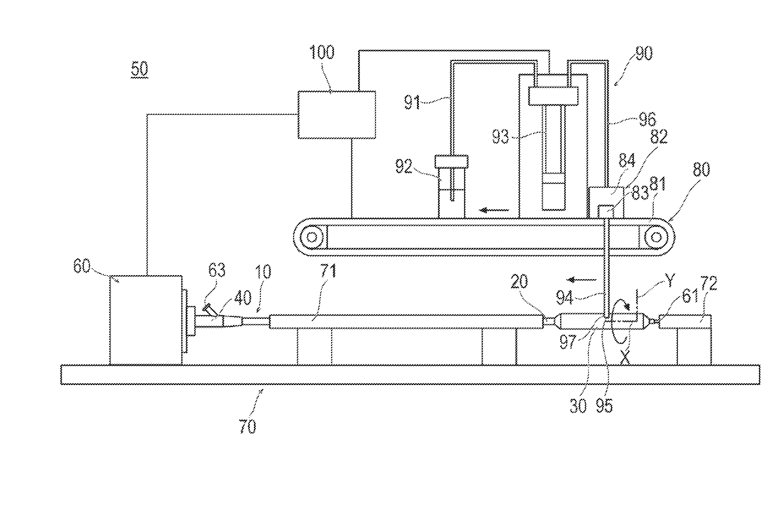
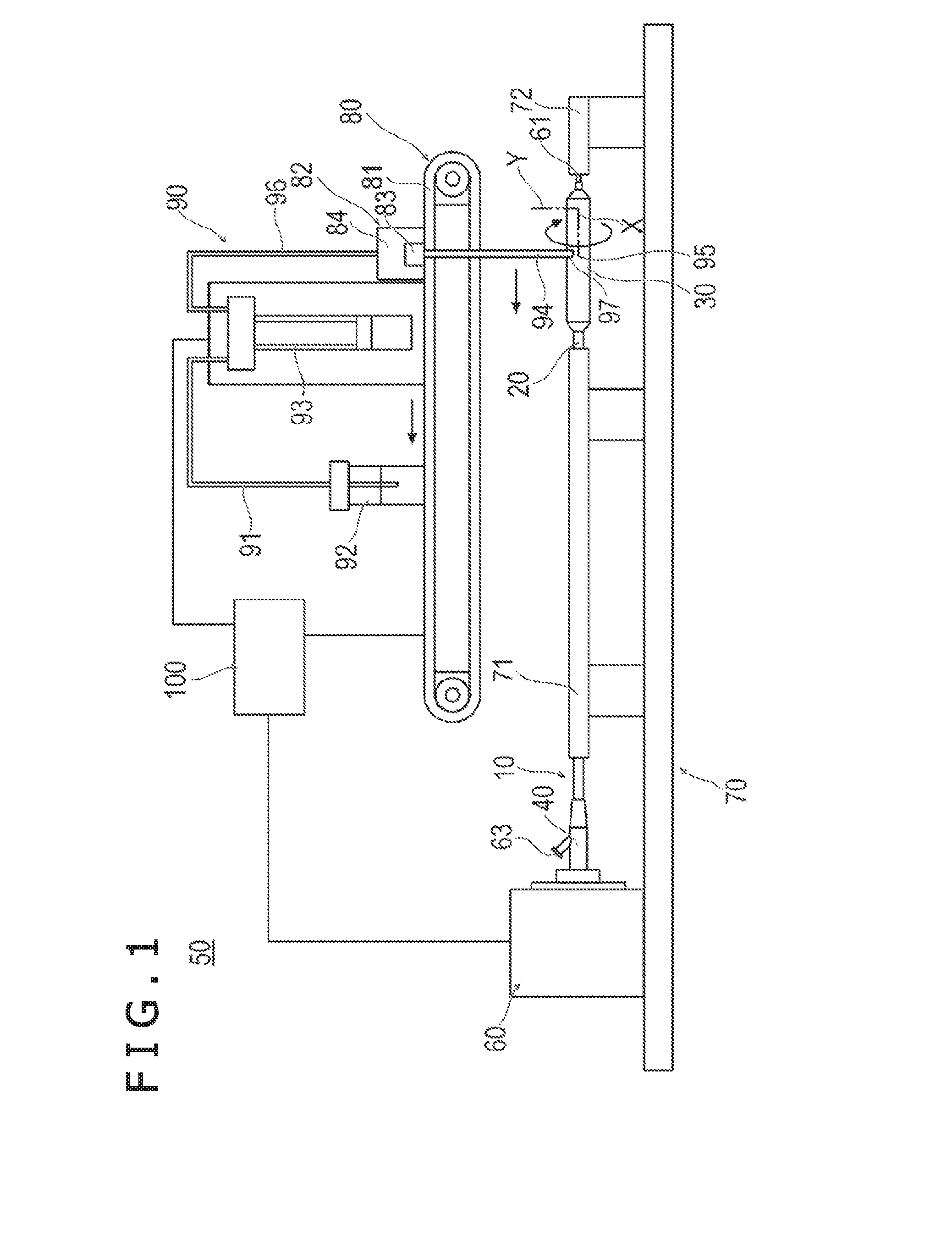
[0183]A balloon catheter (made by Terumo Corporation; the balloon (expandable portion) was formed from nylon elastomer) measuring 3.0 mm in diameter and 20 mm in length (expandable portion) when expanded was provided. The coating solution 1 was applied to the balloon in an expanded state, in such a manner that the solvent of the coating solution was volatilized slowly and that the amount of paclitaxel in the coating would be approximately 3 μg / mm2.

[0184]Specifically, a dispensing tube having an opening portion at a distalmost portion (the dispe...

example 2

(1) Preparation of Coating Solution 2

[0185]70 mg of L-serine ethyl ester hydrochloride and 180 mg of paclitaxel were weighed. To these compounds were added 1.5 mL of anhydrous ethanol, 2.0 mL of acetone, 0.5 mL of tetrahydrofuran, and 1 mL of RO water, to dissolve the compounds, thereby preparing a coating solution 2.

(2) Coating of Balloon with Drug

[0186]A balloon catheter (made by Terumo Corporation; the balloon (expandable portion) was formed from nylon elastomer) measuring 3.0 mm in diameter and 20 mm in length (expandable portion) when expanded was provided. The coating solution 2 was applied to the balloon in an expanded state, in such a manner that the solvent of the coating solution was volatilized slowly and that the amount of paclitaxel in the coating would be approximately 3 μg / mm2.

[0187]Specifically, coating was conducted in the same manner as the method described in Example 1, except that the drug was discharged at a rate of 0.088 μL / second. Thereafter, the thus coated b...


PUM

PropertyMeasurementUnit
Angleaaaaaaaaaa
Angleaaaaaaaaaa
Lengthaaaaaaaaaa

Abstract

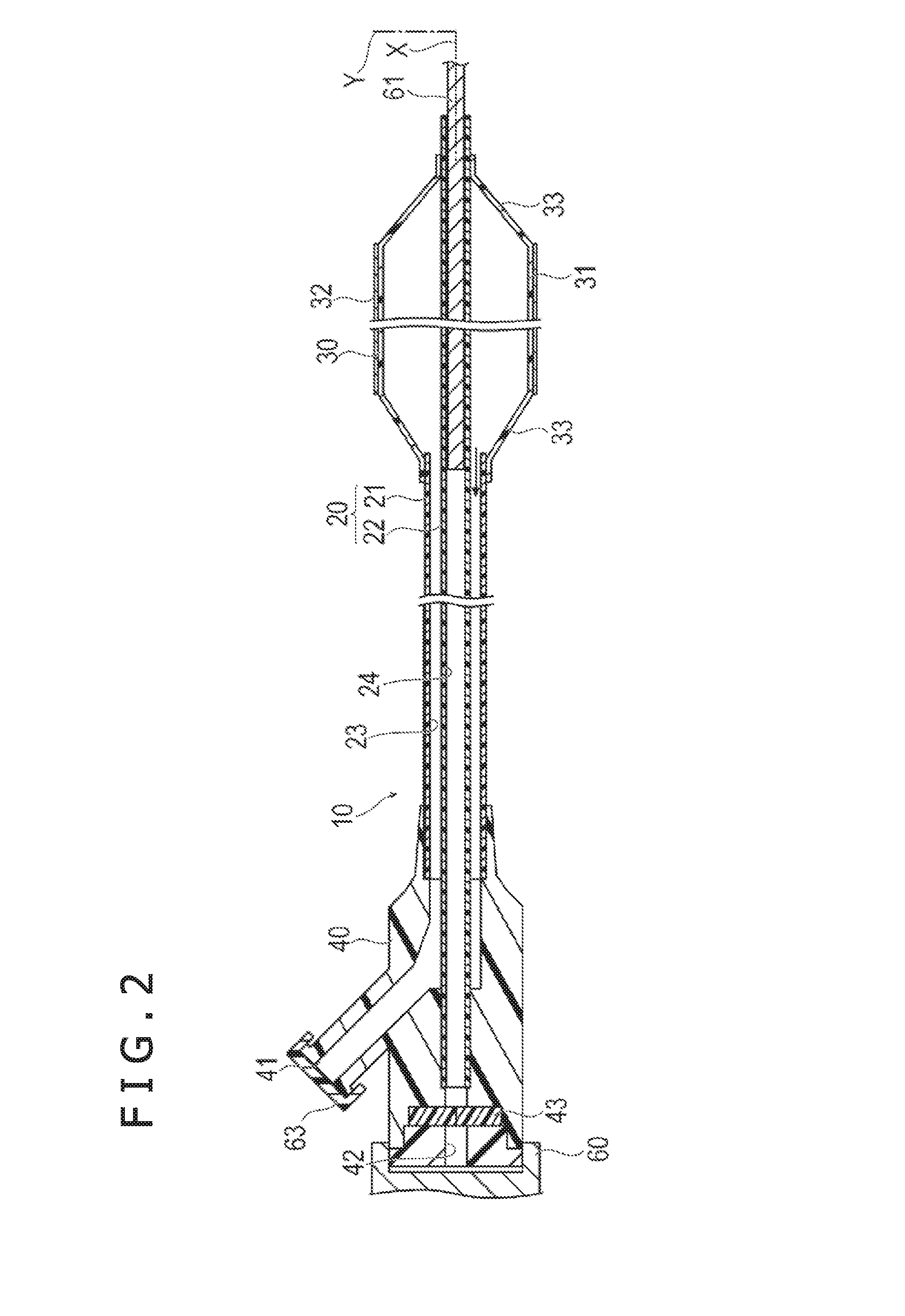
A positioning method for balloon coating by which the thickness and morphological form of a drug in a coating formed on a balloon can be suitably set. This method is a positioning method for balloon coating for forming a coating layer containing a water-insoluble drug on an outer surface of a balloon of a balloon catheter. The positioning method includes a positioning step in which a dispensing tube is moved, from a state of non-contact with the balloon, in a direction intersecting the extending direction of the dispensing tube, and an opening portion-formed end portion side of the dispensing tube formed at its end portion with an opening portion for discharging a coating solution is thereby placed in contact with the outer surface of the balloon.

Description

CROSS-REFERENCES TO RELATED APPLICATIONS[0001]This application is a continuation of International Application No. PCT / JP2015 / 058548 filed on Mar. 20, 2015, which claims priority to Japanese Patent Application No. 2014-075325 filed Apr. 1, 2014, the entire contents of which are incorporated herein by reference as a whole.TECHNICAL FIELD[0002]The present disclosure relates to a positioning method for balloon coating for forming a coating layer containing a drug on a surface of a balloon.BACKGROUND ART[0003]In recent years, balloon catheters have been used for improving lesion affected areas (stenosed parts) generated in body lumens. A balloon catheter normally includes an elongated shaft portion, and a balloon, which is provided on the distal side of the shaft portion and is inflatable in the radial direction. After the balloon in a deflated state is brought to a target site in the body by way of a thin body lumen, the balloon is inflated, whereby the lesion affected area can be pushe...

Claims


Application Information

Patent Timeline
IPC IPC(8): A61M25/10A61L29/16A61L29/08B05C13/02B05C5/02
CPCA61L29/16A61M2025/105A61M2025/1031A61M2207/10A61L2300/416A61L29/08A61M25/10A61M25/1029B05C13/025B05C5/0208A61L2420/02B05B13/0442
Inventor KUROSAKI, YASUOSUZUKI, RYOSUKEFURUICHI, EISUKE
Owner TERUMO KK
Learn More