Energy application apparatus

a technology of energy application and equipment, applied in the field of energy application equipment, can solve the problems of difficult direct communication between the energy source providing ablation energy and the monitoring uni

Active Publication Date: 2015-03-12
KONINKLJIJKE PHILIPS NV
View PDF3 Cites 0 Cited by
  • Summary
  • Abstract
  • Description
  • Claims
  • Application Information

AI Technical Summary

Benefits of technology

[0005]It is regarded as being an object of the present invention to provide an energy application apparatus, an energy application method and a computer program for applying energy to an object, and a sensing apparatus for sensing the object, which allow indicating whether energy is actually applied to the object or not, without necessarily requiring a communication to an energy application unit actually performing the energy application procedure.
[0012]The energy application unit comprises an electrical conductor through which the electrical current is flowing, wherein the current measuring unit is adapted to measure the current flowing through the electrical conductor, for example by using a current transformer, an antenna and / or a magnetic field sensor like a Hall sensor, in particular, a semiconductor Hall sensor. In particular, the current measuring unit can comprise a current transformer being integrated with the electrical conductor, wherein the current transformer comprises a primary element formed by the electrical conductor and a secondary element, which is preferentially electrically insulated from the primary element, and wherein the current measuring unit further comprises a measuring element for measuring the current at the secondary element and for providing the signal based on the current measured at the secondary element. This allows reliably determining the current and thus whether energy is applied or not.
[0015]Preferentially the current measuring unit is adapted to measure current having predefined parameters and to provide the signal based on whether a current having the predefined parameters has been measured. For instance, the current measuring unit can be adapted to detect whether a current is present having parameters within predefined parameter ranges and to provide a binary signal being indicative of whether this current has been detected. In an embodiment, the predefined parameter ranges define current amplitudes and current frequencies. In particular, the current measuring unit can be adapted to detect whether a current is present having an amplitude between 0.1 and 2.0 A, further preferred between 0.13 and 1.8 A, and having a frequency between 400 and 500 kHz and to provide a corresponding binary signal. This reduces the likelihood that an application of energy is wrongly indicated, because a current has been measured, which is not the current used by the energy application unit for applying energy to the object, i.e. the likelihood is reduced that an external interference signal is mistakenly detected as a current applied by the energy application unit.
[0022]The energy application apparatus preferentially further comprises a sensing unit for sensing the object, thereby generating a sensing result, wherein the display unit can be adapted to also show the sensing result. In a preferred embodiment the sensing unit is adapted to ultrasonically sense the object such that an M-mode image is generated, wherein the display unit can be adapted to display the generated M-mode image together with energy application indications indicating at least one of the beginning and the end of the application of energy based on the provided signal. This allows a user like a physician to readily see on the display unit which part of the M-mode image corresponds to an energy application period, during which the energy is applied to the object, and which part of the M-mode image does not correspond to the energy application period.
[0023]The sensing unit can also be adapted to perform the sensing of the object depending on the provided signal being indicative of whether the energy is applied. Preferentially, the sensing unit is adapted to sense the object, if the signal indicates that energy is not applied to the object. In particular, the signal can be indicative of energy application periods, in which the energy is applied and thus the current is measured, and non energy application periods, in which the energy is not applied and thus the current is not measured, wherein the sensing unit can be adapted to sense the object only in non energy application periods. This reduces generally possible disturbances of the sensing of the object by the application of energy, in particular, a corresponding generally possible interference can be prevented.

Problems solved by technology

Interface and communication protocols generally vary depending on the respective manufacturer, the respective device and even depending on the respective version of the device, which can render a direct communication between an energy source for providing the ablation energy and the monitoring unit difficult.

Method used


Image

  • Energy application apparatus
  • Energy application apparatus
  • Energy application apparatus

Examples


Embodiment Construction

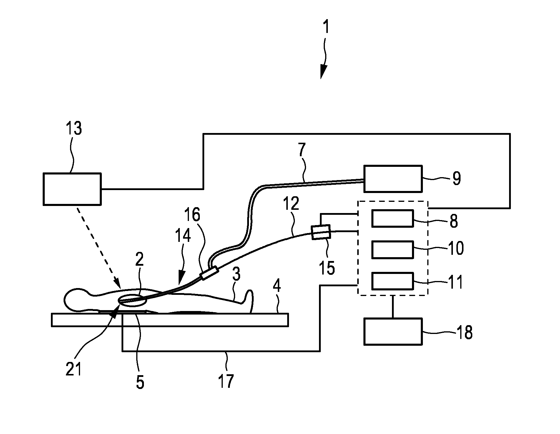
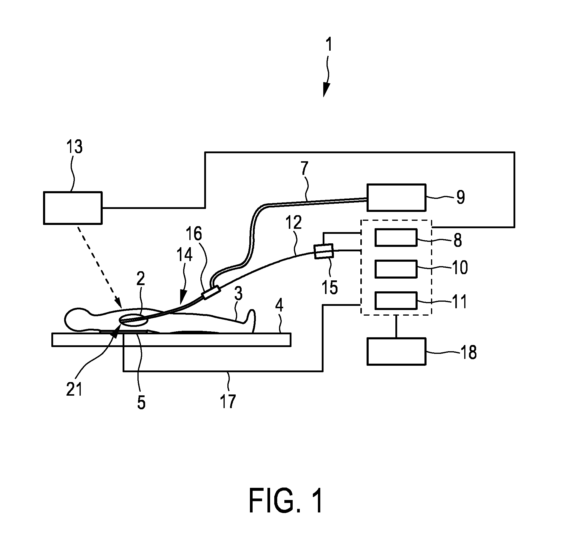
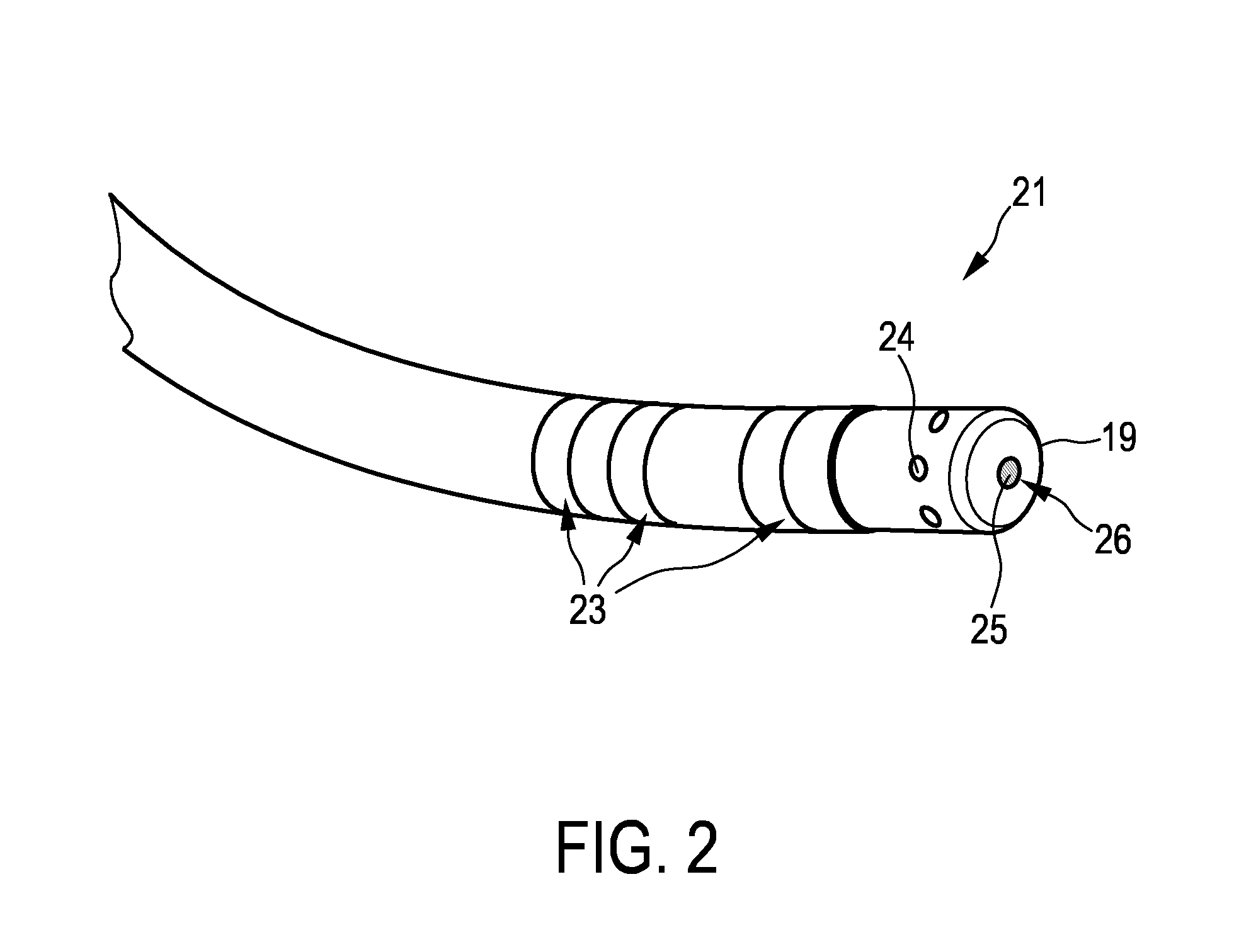
[0042]FIG. 1 shows schematically and exemplarily an embodiment of an energy application apparatus 1 for applying energy to an object. In this embodiment, the energy application apparatus 1 is a cardiac ablation apparatus for performing a cardiac ablation procedure, which comprises an ablation catheter 14 with a catheter handle 16. The tip 21 of the ablation catheter 14 has been introduced into a heart 2 of a person 3 lying on a table 4. The catheter tip 21 is exemplarily shown in more detail in FIG. 2.

[0043]The catheter tip 21 comprises an ablation electrode 19 formed as a cap electrode with irrigation openings 24 and a sensing opening 26. The irrigation openings 24 are arranged along the circumference of the cap electrode 19 and the sensing opening is arranged centrally in the frontal surface of the cap electrode 19. An ultrasound transducer 25 is located within the cap electrode 19 at the opening 26 such that cardiac tissue can be ultrasonically sensed through the sensing opening ...


PUM


Abstract

The invention relates to an energy application apparatus (1) for applying energy to an object (2). An energy application unit applies energy to the object, wherein the energy application unit is adapted to use electrical current for applying the energy. A current measuring unit (15) measures the electrical current used by the energy application unit and provides a signal being indicative of whether the energy is applied to the object based on the measured electrical current. The signal can be used by, for instance, a monitoring unit and / or a display unit for using and / or indicating the information whether energy is actually applied or not, without requiring a direct communication between the energy application unit and the monitoring unit and / or the display unit.

Description

FIELD OF THE INVENTION[0001]The invention relates to an energy application apparatus, an energy application method and a computer program for applying energy to an object. The invention relates further to a sensing apparatus for sensing the object.BACKGROUND OF THE INVENTION[0002]Catheter ablation is a minimally invasive procedure that is widely used for the treatment of cardiac arrhythmias. During a catheter ablation procedure cardiac tissue is locally destroyed, in order to block undesired conduction pathways. The local destruction can be achieved by hyperthermia using, for instance, a radio frequency (RF) source, a laser or a high-intensity focused ultrasound (HIFU) source as energy source or by hypothermia in case of cryoablation. The energy is generally provided via a tip of an ablation catheter. The ablation procedure can be monitored by a monitoring unit comprising a display unit, on which the monitoring result can be shown.[0003]In order to allow a user like a physician to k...

Claims


Application Information

Patent Timeline
Patent Type & Authority Applications(United States)
IPC IPC(8): A61B18/12A61B19/00A61B18/14
CPCA61B18/12A61B18/1492A61B19/5225A61B2019/5276A61B2018/00827A61B2018/00898A61B2018/00642A61B2018/00577A61B2018/00904A61B2018/00982A61B90/06A61B2090/065A61B2090/378
Inventor BUDZELAAR, FRANCISCUS PAULUS MARIAHARKS, GODEFRIDUS ANTONIUSFOKKENROOD, STEVEN ANTONIE WILLEM
Owner KONINKLJIJKE PHILIPS NV
Why Eureka
Try Eureka