Eureka AIR delivers breakthrough ideas for toughest innovation challenges, trusted by R&D personnel around the world.

Saw Band With a Profiled Back

Inactive Publication Date: 2015-03-19
WIKUS SAGENFAB WILHELM H KULLMANN
View PDF2 Cites 8 Cited by
  • Summary
  • Abstract
  • Description
  • Claims
  • Application Information

AI Technical Summary

Benefits of technology

The patent describes a saw band with a tilting movement that produces a cold work hardened zone in the material to be cut through aggressive cutting behavior. The saw band has a profiled back that results in varying cutting forces, reducing wear and tear. The reduced length of the saw band also results in a good surface quality with reduced roughness values and good straightness of the cut workpiece. The tooth supporting body and the base of the teeth are made of metal, while the cutting edge and tips of the teeth are made of hard materials such as tool steel or abrasive cutting materials. The saw band can also be used for cutting other materials like wood or plastics.

Problems solved by technology

Due to the aggressive cutting behavior, this cold work hardened zone is undercut.

Method used


Image

  • Saw Band With a Profiled Back
  • Saw Band With a Profiled Back
  • Saw Band With a Profiled Back

Examples


Embodiment Construction

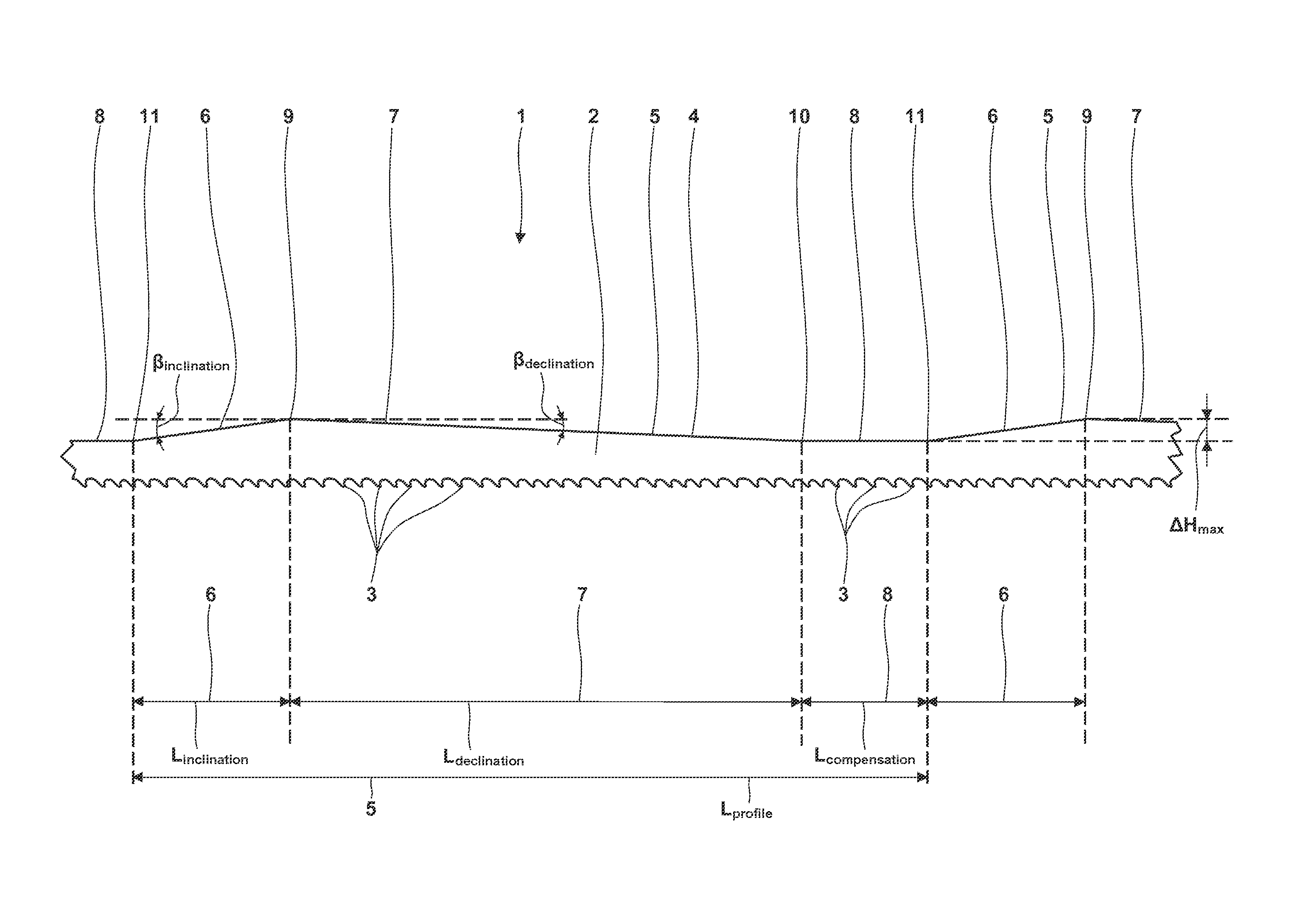
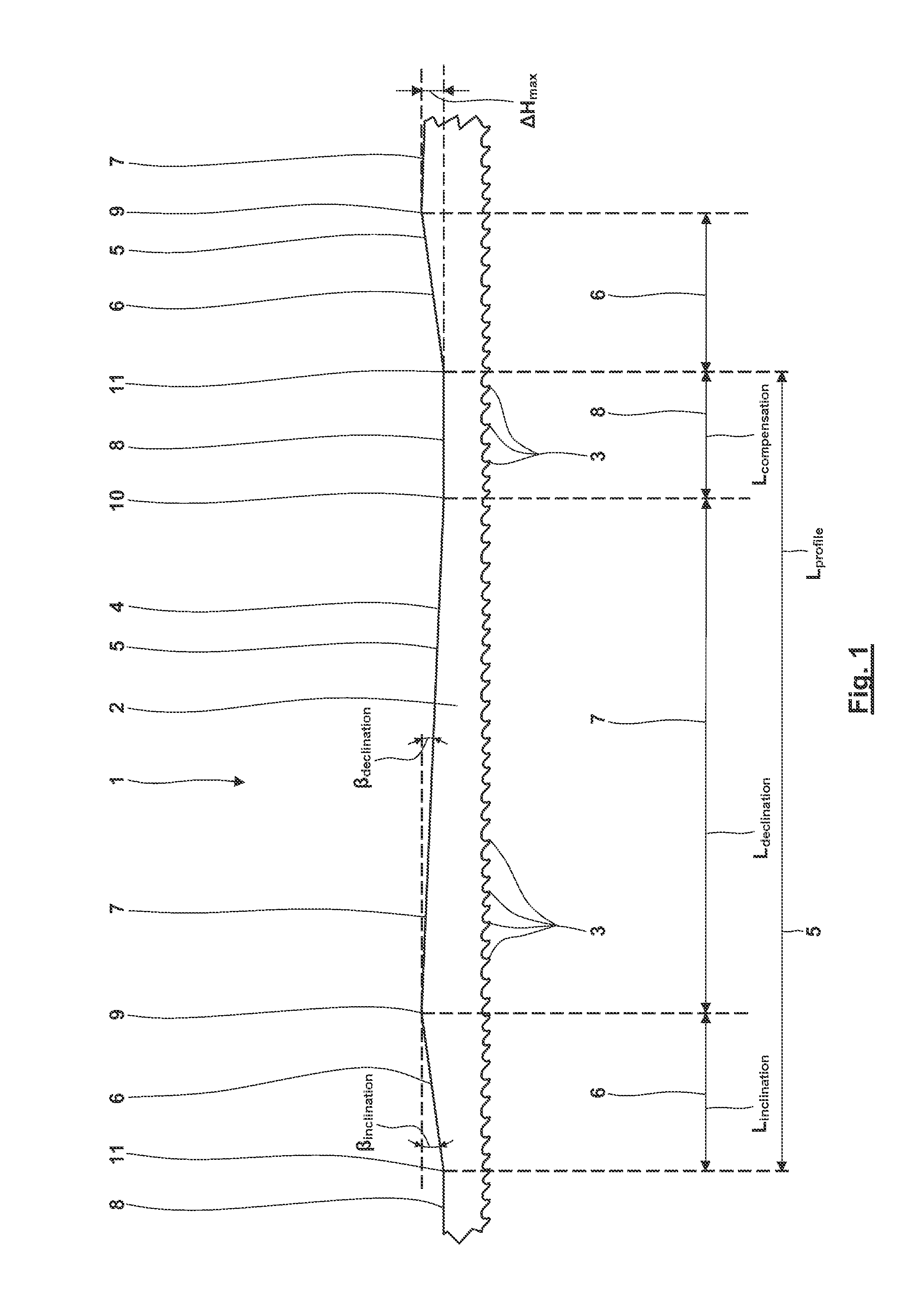
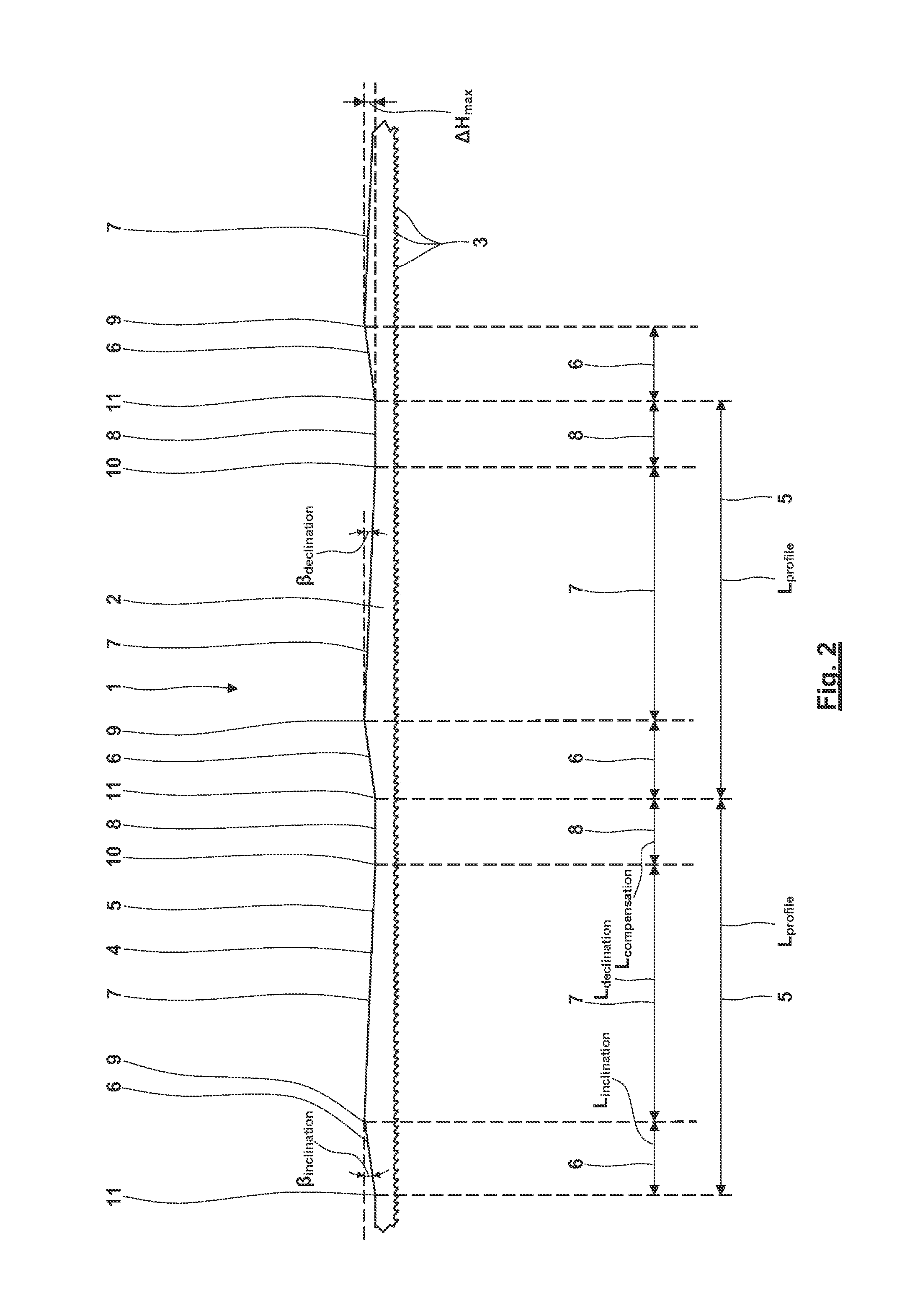
[0047]FIGS. 1-12 illustrate different views of parts of an exemplary embodiment of a novel saw band 1.

[0048]The views are true to scale such that the geometric relations between the single elements of the saw band can be determined from the drawings. This also applies with one restriction to the profiled back portion illustrated in FIGS. 1-11. This portion is enlarged by the scale of 15:1 in the direction perpendicular to the direction of movement of the saw band illustrated in the drawings (i.e. the usual direction Y) to improve recognizability of the profiling of the back of the band. This enlargement only relates to the profiled section of the back of the band and thus not to the distance between the lowest point of the back of the band and the teeth.

[0049]FIG. 1 illustrates a part of an elongated saw band 1 which is to be seen from the jagged lines in the left portion and the right portion of the illustration in FIG. 1. The saw band 1 includes a tooth supporting body 2 and a plu...


PUM

PropertyMeasurementUnit
Lengthaaaaaaaaaa
Lengthaaaaaaaaaa
Fractionaaaaaaaaaa

Abstract

A saw band (1) includes a tooth supporting body (2), a plurality of teeth (3) being located at the tooth supporting body (2) and a back (4) being located opposite to the teeth (3). The back (4) includes a profiled back portion (5). The profiled back portion (5) includes an inclination portion (6), a declination portion (7) and a compensation portion (8). The declination portion (7) is located next to the end of the inclination portion (6) and the compensation portion (8) is located next to the end of the declination portion (7). Alternatively, the inclination portion (6) is located next to the end of the declination portion (7) and the compensation portion (8) is located next to the end of the inclination portion (6), the length of the compensation portion (8) being shorter than length of the inclination portion (6) and the length of the declination portion (7).

Description

CROSS REFERENCE TO RELATED APPLICATIONS[0001]This application claims priority to co-pending German Patent Application No. DE 10 2013 110 120.8 entitled “Sägeband mit profiliertem Bandrücken”, filed Sep. 13, 2013.FIELD OF THE INVENTION[0002]The present invention generally relates to a saw band including a tooth supporting body and a plurality of teeth being arranged at the tooth supporting body. Opposite to the teeth, the saw band includes a back having a profiled back portion.[0003]The back of the band thus does not extend in the usual straight direction of movement of the band, but it is designed to be profiled, and it includes a plurality of portions extending at different angles with respect to the usual straight direction of movement of the band.BACKGROUND OF THE INVENTION[0004]Saw bands having a straight and non-profiled back extending in the usual straight direction of movement of the band are generally known in the art. Such a design results in a uniform feed rate, always the...

Claims


Application Information

Patent Timeline
IPC IPC(8): B23D61/12
CPCB23D61/123Y10T83/9317B23D61/12B27B33/06
Inventor KULLMANN, JOERG H.GLEIM, PATRICKSIEL, CHRISTOPH
Owner WIKUS SAGENFAB WILHELM H KULLMANN
Why Eureka
Eureka Blog
Learn More