Rotation transmission device

Active Publication Date: 2015-03-19
NTN CORP
View PDF3 Cites 9 Cited by
  • Summary
  • Abstract
  • Description
  • Claims
  • Application Information

AI Technical Summary

Benefits of technology

[0031]According to the present invention, with the electromagnetic coil of the electromagnetic clutch disengaged and thus the flange of the control retainer in contact with the open end surface of the outer ring, the anti-rotation means prevents relative rotation between the outer ring and the control retainer. In particular, the anti-rotation means prevents rotation of the control retainer relative to the outer ring while th

Problems solved by technology

If the outer race and the inner race should actually rotate relative to each other in the stand-by or engaged position, this could move

Method used


Image

  • Rotation transmission device
  • Rotation transmission device
  • Rotation transmission device

Examples


Embodiment Construction

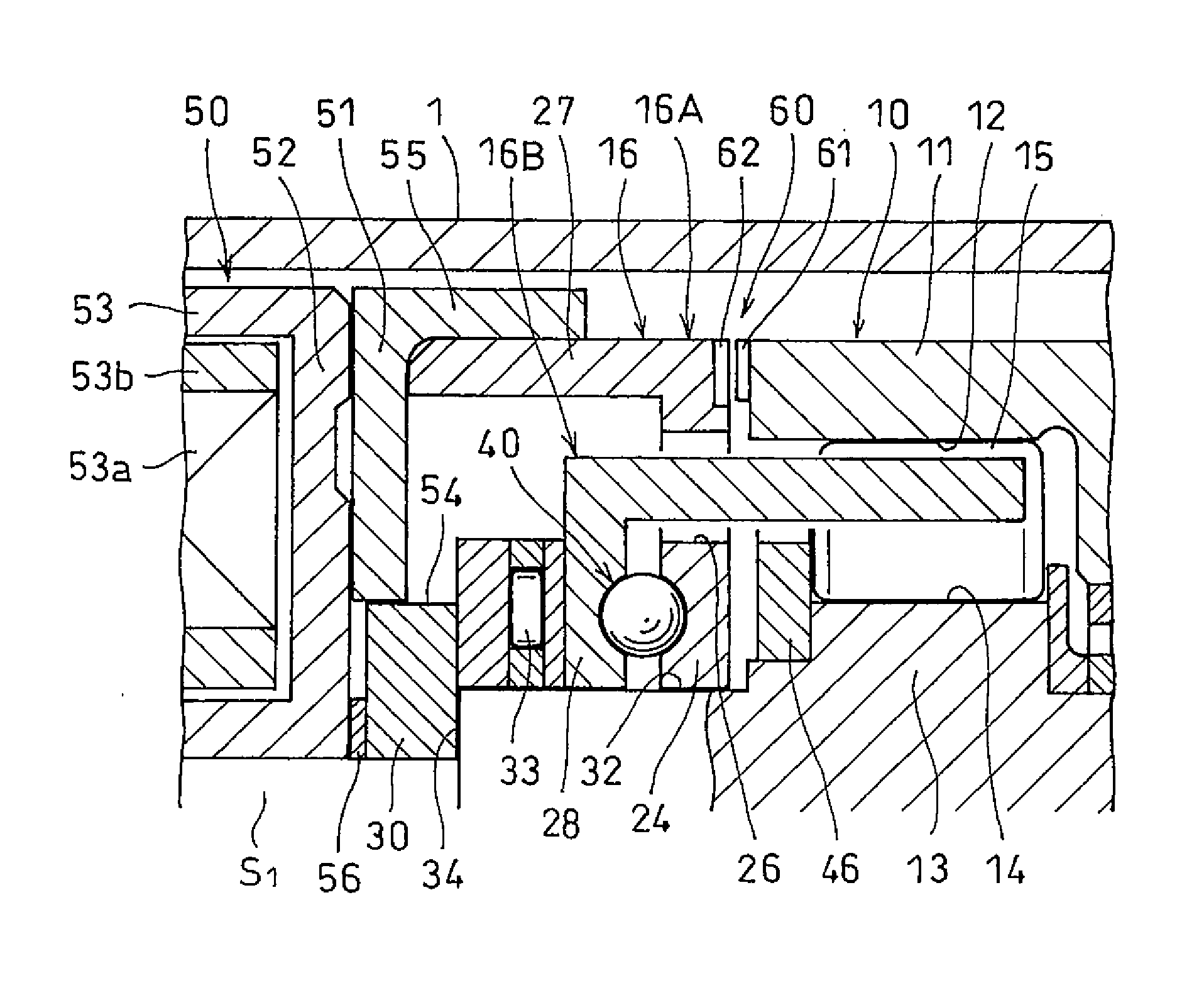
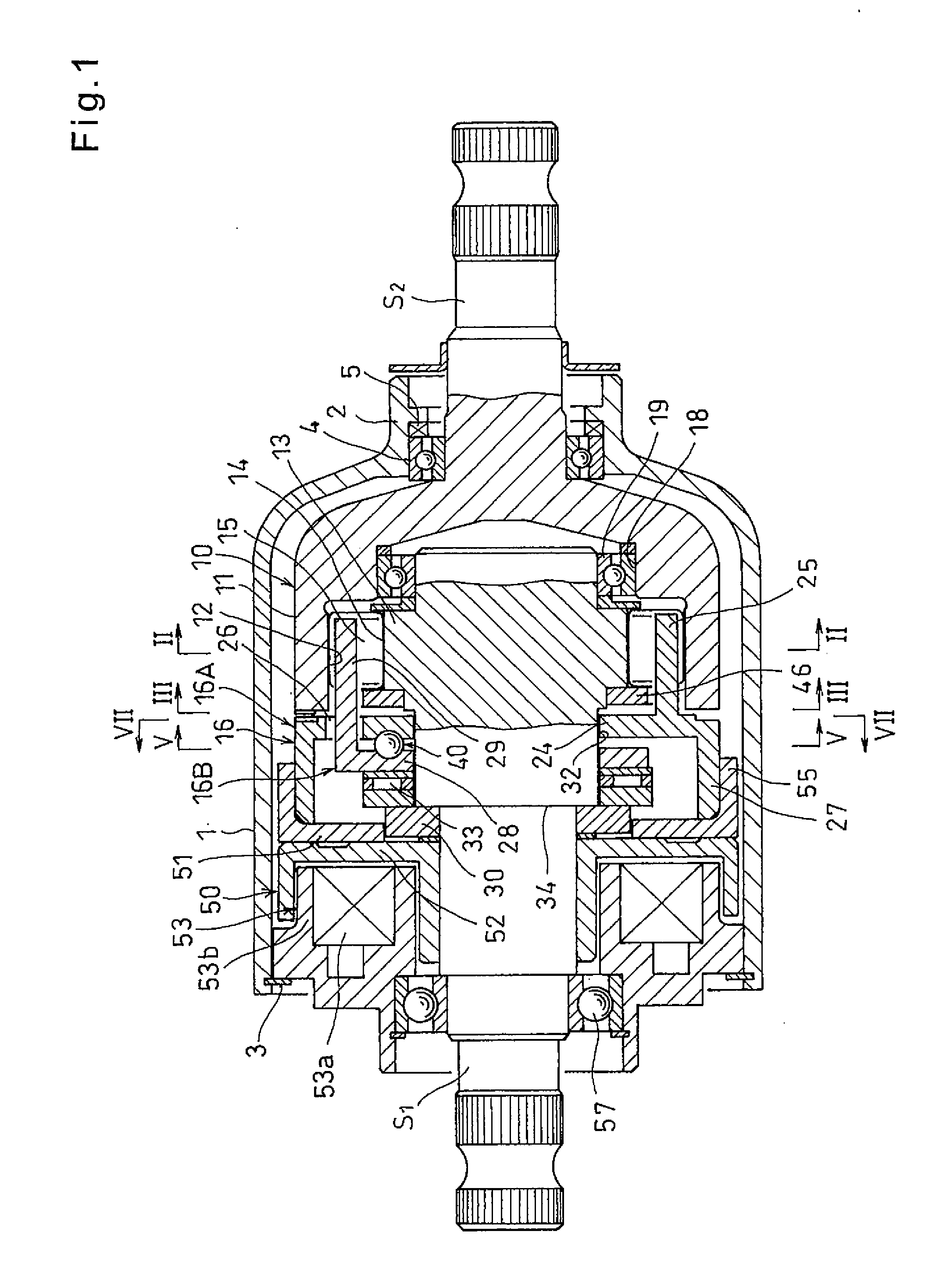
[0053]Now the embodiment of the present invention is described with reference to the drawings. FIG. 1 shows a rotation transmission device embodying the present invention. As shown, the rotation transmission device includes an input shaft S1, an output shaft S2 arranged coaxial with the input shaft S1, a housing 1 covering the opposed end portions of the shafts S1 and S2, a two-way clutch 10 mounted in the housing 1 and configured to selectively transmit the rotation of the input shaft S1 to the output shaft S2, and an electromagnetic clutch 50 for selectively engaging and disengaging the two-way clutch 10.

[0054]The housing 1 is a cylindrical member formed with a small-diameter bearing tube 2 at a first end thereof. A snap ring 3 is mounted on the inner periphery of the housing 1 at the second end of the housing 3 opposite from the first end, preventing separation of the electromagnetic clutch 50.

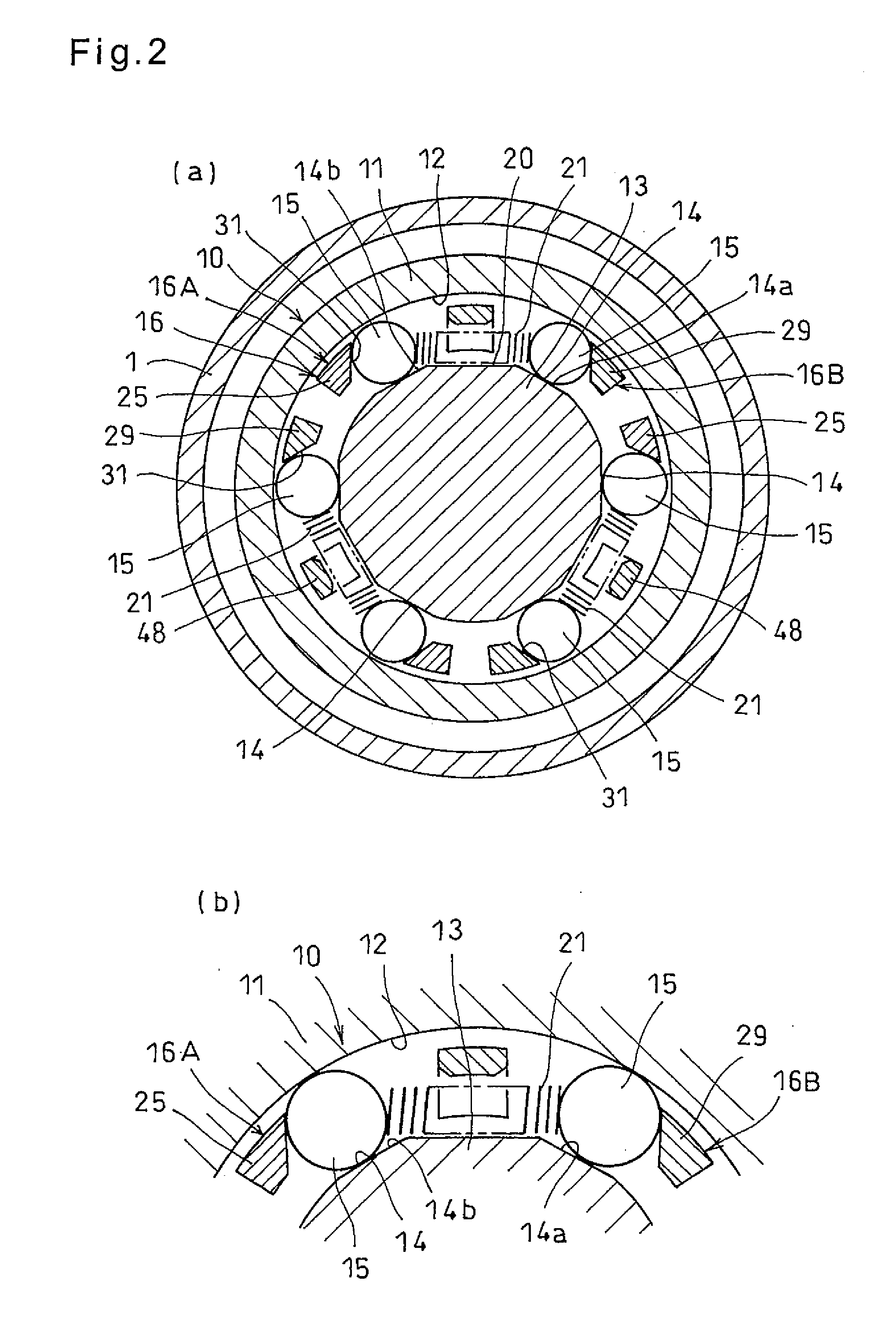
[0055]As shown in FIGS. 1 and 2, the two-way clutch 10 includes an outer ring 11 provid...


PUM


Abstract

A rotation transmission device includes a two-way clutch which is selectively engaged and disengaged by an electromagnetic clutch. The two-way clutch includes a control retainer and a rotary retainer. The control retainer and the rotary retainer have flanges and bars formed on outer peripheral portions of the respective flanges and arranged so as to circumferentially alternate with each other with pockets defined between adjacent bars. Two rollers are received in each pocket. When the control retainer and the rotary retainer are rotated relative to each other, the rollers are adapted to be pushed by the bars to the disengaged position. An anti-rotation arrangement is provided on opposed surfaces of an outer ring and the control retainer member. The anti-rotation arrangement is adapted to prevent the control retainer from rotating relative to the outer ring while the rollers are in engagement, thereby preventing the rollers from moving to the neutral position.

Description

TECHNICAL FIELD[0001]This invention relates to a rotation transmission device which can selectively transmit rotation of one member to another member.BACKGROUND ART[0002]One known rotation transmission device which can selectively transmit rotation of a driving shaft to a driven shaft includes a two-way clutch and an electromagnetic clutch for selectively engaging and disengaging the two-way clutch.[0003]The rotation transmission device disclosed in the below-identified Patent document 1 includes an outer ring, an inner ring mounted inside the outer ring, and a control retainer and a rotary retainer each having bars and mounted between the inner and outer rings such that the bars of the control retainer are arranged circumferentially alternating with the bars of the rotary retainer, whereby pockets are defined between circumferentially adjacent pairs of the bars of the respective retainers. The rotation transmission device further includes opposed pairs of rollers, each pair being m...

Claims


Application Information

Patent Timeline
IPC IPC(8): F16D41/08F16D27/118
CPCF16D27/118F16D41/088F16D41/08F16D41/105F16D2023/123
Inventor AKIYOSHI, KOJISATO, KOJIKITAYAMA, NAOTSUGUSAITO, TAKAHIDE
Owner NTN CORP
Why Eureka
Try Eureka