Portable radiation imaging apparatus and portable radiation imaging system

a radiation imaging apparatus and portable technology, applied in the field of portable radiation imaging apparatus and portable radiation imaging system, can solve the problems of inability to detect accurately, and inability to prevent roaming problems, so as to achieve stable communication quality and prevent failure

Active Publication Date: 2015-03-19
FUJIFILM CORP
View PDF6 Cites 12 Cited by
  • Summary
  • Abstract
  • Description
  • Claims
  • Application Information

AI Technical Summary

Benefits of technology

[0034]According to the present invention, the trigger signal is obtained while the portable radiation imaging apparatus stands still. At this time, one of the access points is determined as the appropriate access point based on the field intensity. The field

Problems solved by technology

Failure in receiving the additional imaging order requires the radiologic technologist to return to the hospital room of the patient who has finished radiation imaging, and perform re-imaging of the patient.
However, experiments revealed that the sole provision of the roaming function as disclosed in the U.S. Patent Application Publication No. 2010/0169423 cannot prevent roaming problems such as failure in switching the connection to an appropriate access point.
However, in actual cases, the console often maintains its connection to the access point on the first floor and does not switch its connection to the access point on the second floor in a case where the radio waves from the access point on the first floor reach the second floor.
In this case, the field intensities vary with the move of the mobile radiography unit, so that the detection may not be accurate.
This causes the roaming problem, namely, the connection to the currently-connected access point is maintained despite the presence of another appropriate access point.
There is another factor for causing th

Method used


Image

  • Portable radiation imaging apparatus and portable radiation imaging system
  • Portable radiation imaging apparatus and portable radiation imaging system
  • Portable radiation imaging apparatus and portable radiation imaging system

Examples


first embodiment

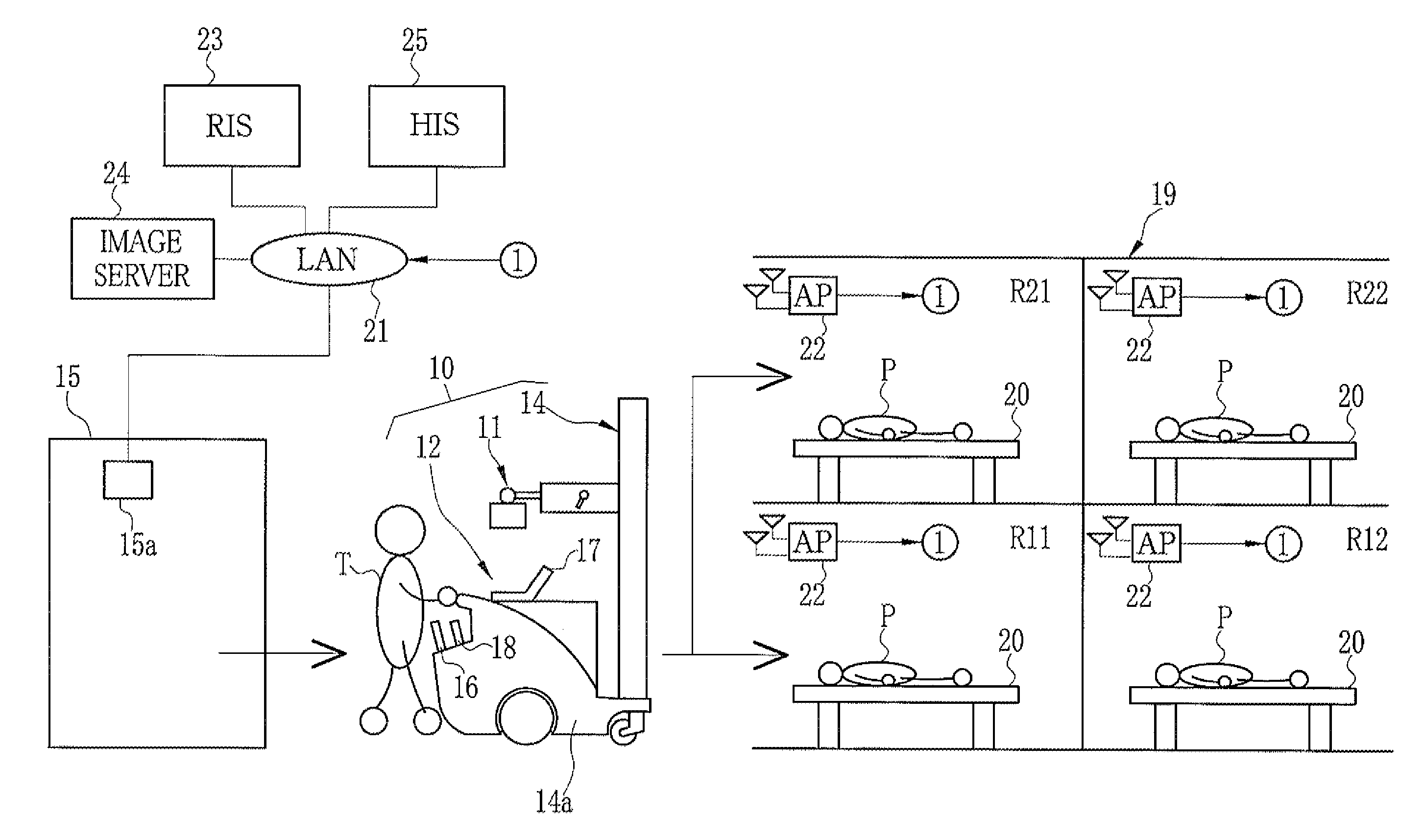
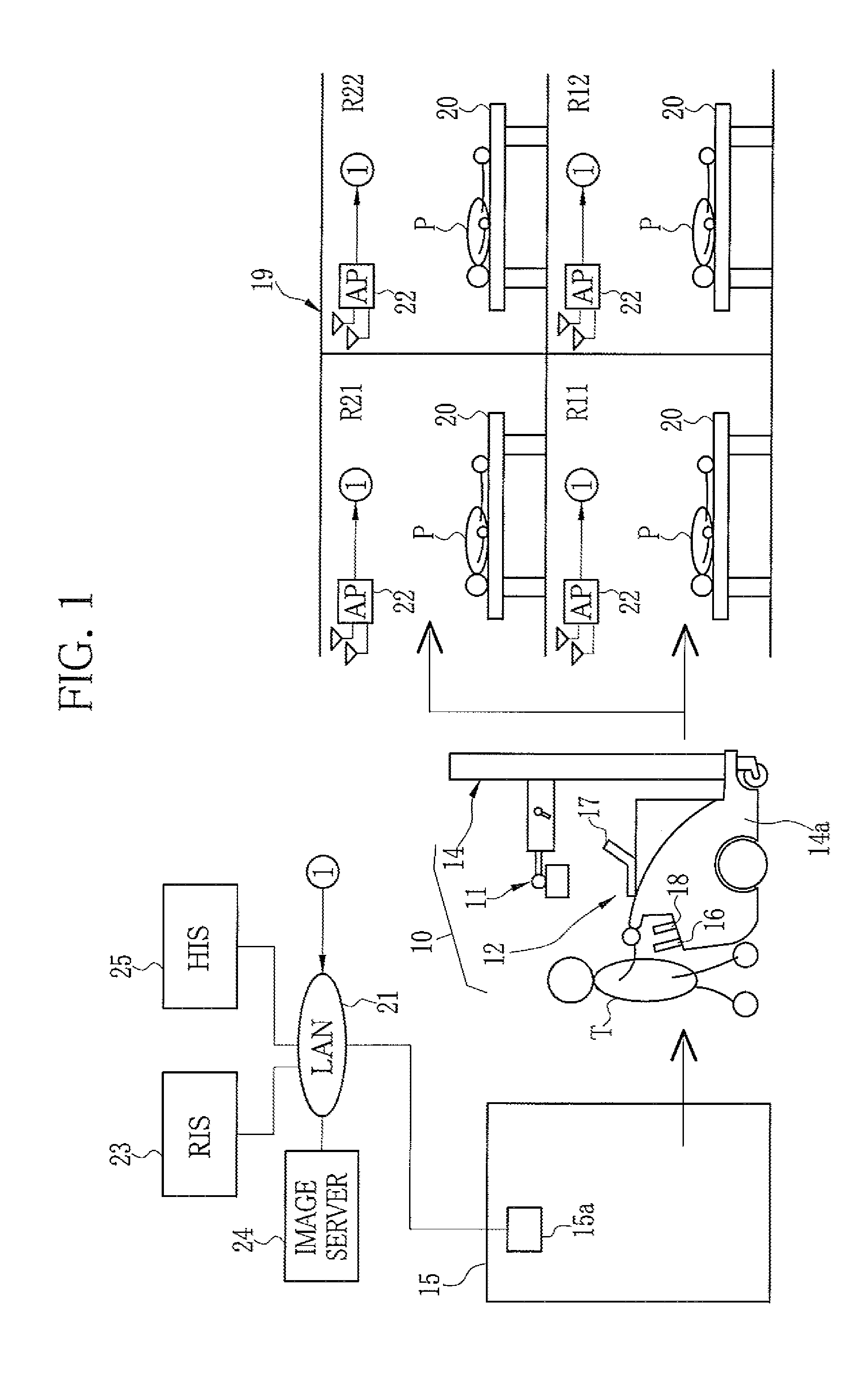
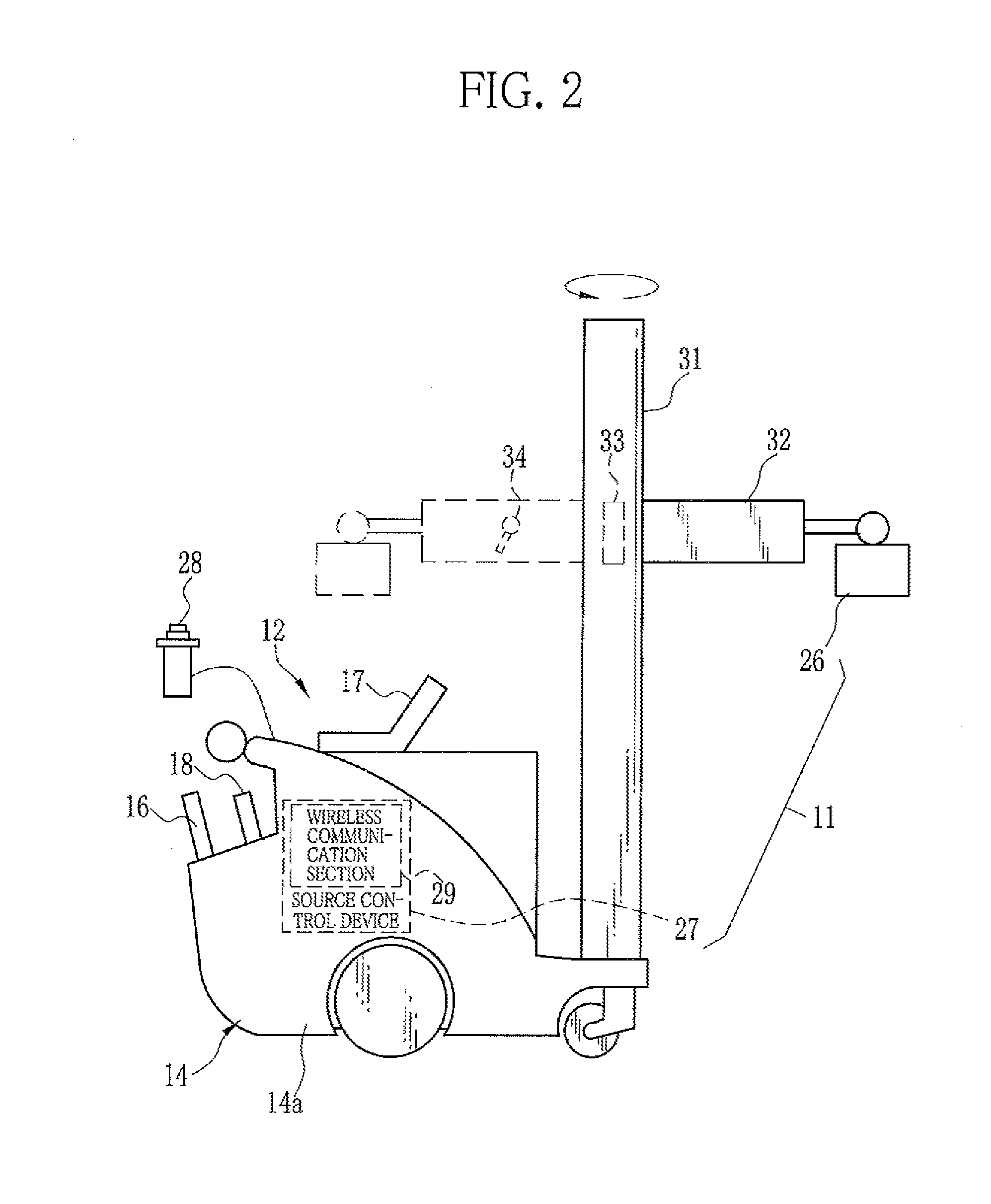
[0056]In FIG. 1, a portable X-ray imaging system (hereinafter simply referred to as the X-ray imaging system) 10 is composed of a portable X-ray generating apparatus (hereinafter, simply referred to as the X-ray generating apparatus) 11 and a portable X-ray imaging apparatus (hereinafter, simply referred to as the X-ray imaging apparatus) 12. The X-ray generating apparatus 11 is a movable (mobile) X-ray generating apparatus mounted on a movable cart 14a that moves with wheels. The X-ray generating apparatus 11 together with the cart 14a is referred to as a mobile radiography unit 14. The X-ray imaging apparatus 12 has an electronic cassette 16, a portable console 17, and a functional unit 18, and is mounted on the mobile radiography unit 14. The mobile radiography unit 14 is placed in a cart parking area 15 in medical facilities or a hospital when not in use. At the time of portable or bedside imaging, the portable X-ray imaging apparatus 12 is mounted on the mobile radiography unit...

second embodiment

[0139]In the above embodiment, the trigger signal is transmitted at the timing of the unlocking operation of the mobile radiography unit 14, by way of example. The timing of transmitting the trigger signal is not limited to the above as long as the trigger signal is transmitted while the X-ray imaging apparatus 12 stands still. It is preferable that the trigger signal is transmitted before the single imaging ends, as in the case of the trigger signal transmitted at the timing of the unlocking operation. Other than that, the trigger signal may be transmitted as described in a second embodiment illustrated in FIG. 13, for example. The second embodiment describes an example in which the trigger signal is generated when the electronic cassette 16 shifts to the “ready” state. Also at this timing, the X-ray imaging apparatus 12 is considered to be still. Also in this case, the trigger signal is transmitted before the single imaging ends.

[0140]The steps in a dotted box in FIG. 13 are the o...

third embodiment

[0143]A third embodiment illustrated in FIG. 14 is an example in which the trigger signal is generated when the console 17 is operated. Also at this timing, the X-ray imaging apparatus 12 is considered to be still. In the third embodiment, for example, the CPU 17C generates the trigger signal when the imaging conditions are set through the operation screen 61 (S1110). Also in this example, the CPU 17C corresponds to the first transmitting section, in a manner similar to the second embodiment. Based on the trigger signal, the appropriate AP 22 is determined and the connection to the appropriate AP 22 is established (S1111) and the imaging order delivery request is transmitted (S1112).

[0144]The operation of the console 17 may be, for example, choosing one of imaging orders 68 in the order display area 66, instead of setting the imaging conditions. In a case where the console 17 is a collapsible notebook computer as described in this example, the operation of the console 17 may be open...


PUM


Abstract

A portable X-ray imaging apparatus has an electronic cassette and a console capable of receiving an imaging order. The console has a wireless communication section, a trigger signal obtaining section, a connection determining section, a switching section, and a delivery requesting section. The wireless communication section receives radio waves and connects itself to an access point (AP). The trigger signal obtaining section obtains a trigger signal while the mobile radiography unit stands still. At the time of obtaining the trigger signal, the connection determining section determines one of the APs as an appropriate AP based on field intensity. The switching section switches the connection to the appropriate AP. Then, the delivery requesting section transmits a delivery request for the imaging order.

Description

CROSS-REFERENCE TO RELATED APPLICATIONS[0001]The present application claims priority under 35 U.S.C. §119 to Japanese Patent Application No. 2013-192467, filed Sep. 17, 2013 and Japanese Patent Application No. 2014-029990, filed Feb. 19, 2014. Each of the above applications is hereby expressly incorporated by reference, in its entirety, into the present application.BACKGROUND OF THE INVENTION[0002]1. Field of the Invention[0003]The present invention relates to a portable radiation imaging apparatus and a portable radiation imaging system.[0004]2. Description Related to the Prior Art[0005]In a medical field, radiation imaging systems which utilize radiation (for example, X-rays) are known. The X-ray imaging system comprises an X-ray generating apparatus and an X-ray imaging apparatus. The X-ray generating apparatus generates X-rays. The X-ray imaging apparatus detects the X-rays that passed through the subject (patient) and thereby captures an X-ray image of the subject. The X-ray ge...

Claims


Application Information

Patent Timeline
IPC IPC(8): A61B6/00H04W76/04H04W76/02H04W88/08
CPCA61B6/563A61B6/4405H04W76/02H04W76/04H04W88/08A61B6/54H04W76/10H04W76/20
Inventor TSUBOTA, KEIJINISHINO, NAOYUKIOHTA, YASUNORI
Owner FUJIFILM CORP
Why Eureka
Try Eureka