Shoe Sole Having Outsole and Midsole

a technology of outsole and midsole, which is applied in the direction of footwear, footwear, applications, etc., can solve the problems of lowering the athletic function, affecting the athletic function of the foot sole, and the rigidity of the sole as a whole upon bending excessively, so as to reduce the athletic function, reduce the weight, and reduce the bendability of the foo

Active Publication Date: 2015-03-26
ASICS CORP
View PDF66 Cites 80 Cited by
  • Summary
  • Abstract
  • Description
  • Claims
  • Application Information

AI Technical Summary

Benefits of technology

[0007]Also in the first patent document, the lateral portion of the midsole having a high hardness is rolled up, and such a roll-up portion serves to prevent a lateral shake.
[0026]Incidentally, a rubber outsole and a stabilizer made of a non-foamed body of a resin have been used to support the lateral side of the foot from the side. However, these members are harder and heavier than the foamed body of a resin of the midsole, and will therefore likely lead to a decrease in the athletic functionality such as foot bendability. In contrast, in the present shoe sole, the roll-up portion is formed by the midsole made of a foamed body of a resin, thereby realizing an appropriate hardness and a light weight, and therefore it will unlikely lead to a decrease in the bendability of the foot or a decrease in the athletic functionality.

Problems solved by technology

However, there is a hard outsole layer underneath, and if the upper-layer midsole apart from the bending neutral axis upon bending the sole alone is hard, the bending rigidity of the sole as a whole upon bending may be excessively high.
As a result, the bendability of the sole may lower, thereby lowering the athletic functionality.
Also, if the upper-layer midsole is hard, since the layer close to the foot sole is hard, the impact of landing is likely to occur on the foot sole.

Method used


Image

  • Shoe Sole Having Outsole and Midsole
  • Shoe Sole Having Outsole and Midsole
  • Shoe Sole Having Outsole and Midsole

Examples


embodiment

[0084]The present invention will be understood more clearly from the following description of preferred embodiments taken in conjunction with the accompanying drawings. Note however that the embodiments and the drawings are merely illustrative, and should not be relied upon in defining the scope of the present invention. The scope of the present invention shall be defined only by the appended claims. In the accompanying drawings, like reference numerals denote like components throughout the plurality of figures.

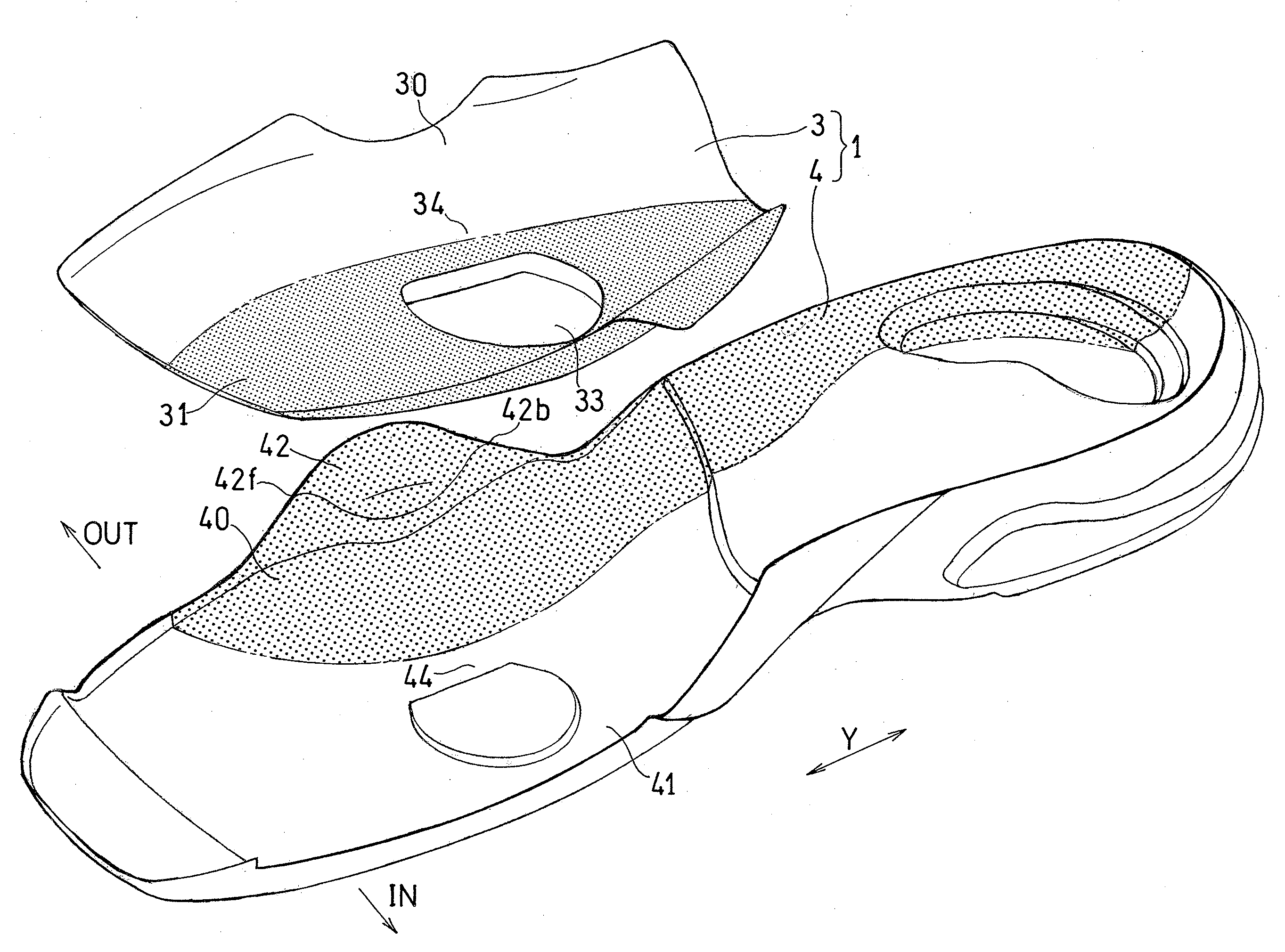
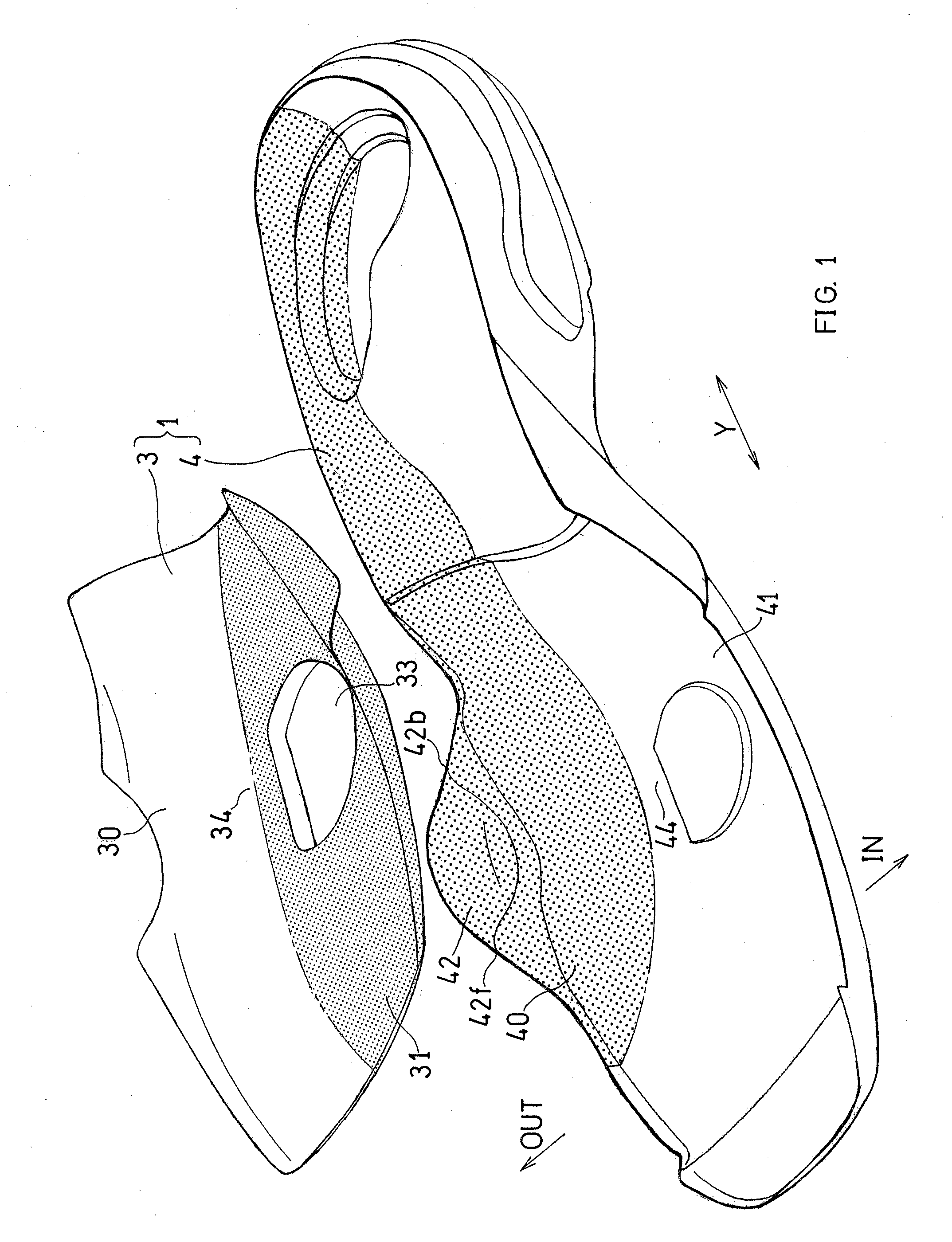
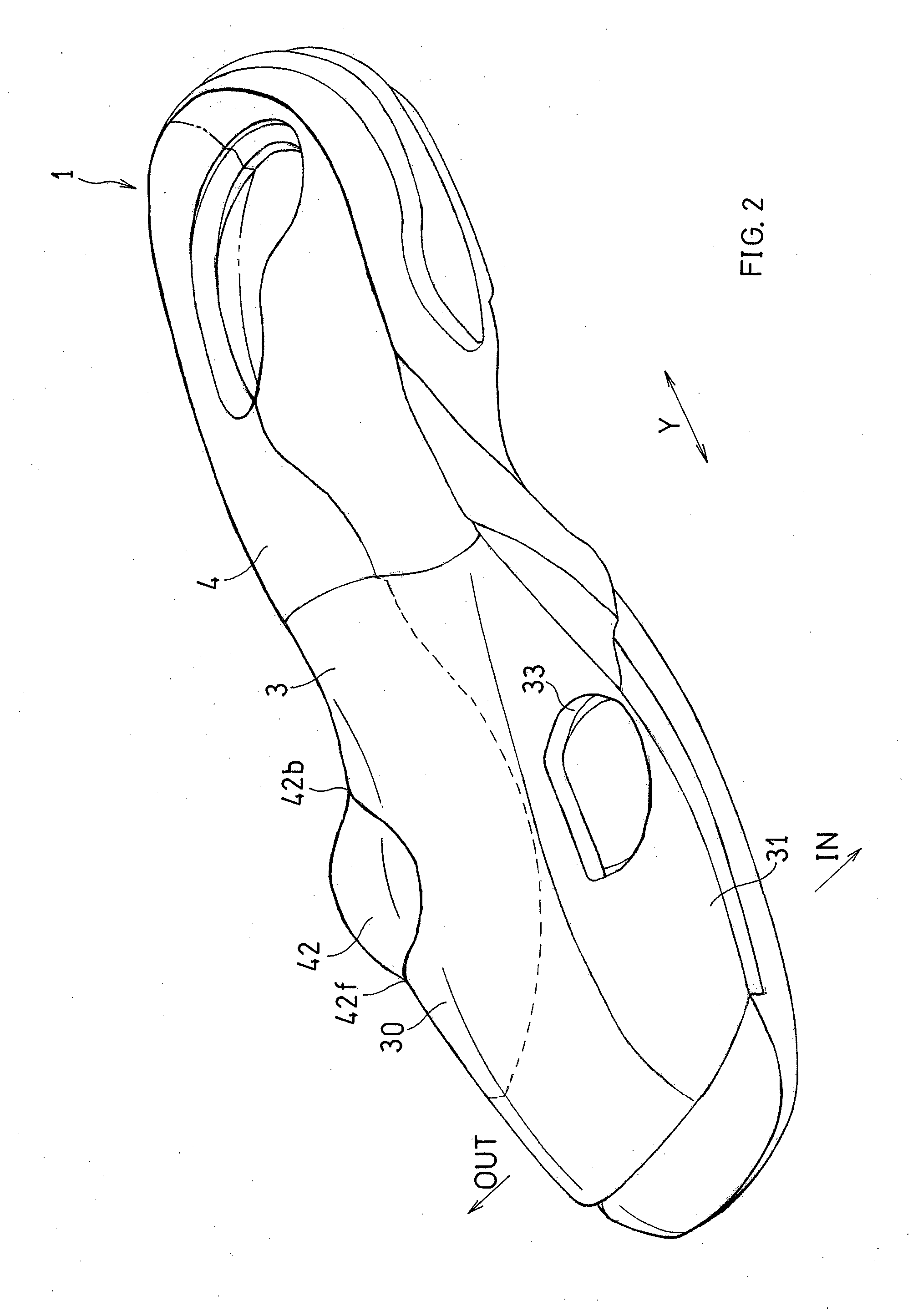
[0085]One embodiment of the present invention will now be described with reference to FIGS. 1 to 6D.

[0086]As shown in FIGS. 1 to 3A, the shoe sole is suitable for tennis shoes for women, for example, including an outsole 2 having a tread surface to be in contact with the road surface, and a midsole 1 arranged on the outsole 2.

[0087]The midsole 1 is formed by, for example, a material suitable for impact absorption such as a foamed body of a resin such as EVA (ethylene-vinyl ac...


PUM


Abstract

A shoe sole including an outsole 2 and a midsole 1, wherein: the midsole 1 includes a lower midsole 4 of a lower layer formed by a foamed body of a resin, and an upper midsole 3 of an upper layer formed by a foamed body of a resin and arranged on the lower midsole 4; a lateral roll-up portion 42 for supporting a lateral side of a foot from a side of the foot is formed integrally with the lower midsole 4; a hardness of a lateral portion 40 of the lower midsole 4 including the lateral roll-up portion 42 is a first hardness; a hardness of a medial portion 41 of the lower midsole 4 is a second hardness lower than the first hardness; a hardness of a lateral portion 30 of the upper midsole 3 is a third hardness lower than the first hardness; and a part or a whole of the high-hardness lateral roll-up portion 42 is protruding in an upward direction past the upper midsole 3 on a lateral side of the upper midsole 3 so that the lateral side of the foot is supported by the lateral roll-up portion 42 from the side of the foot without being supported by the upper midsole 3 from the side of the foot.

Description

TECHNICAL FIELD[0001]The present invention relates to a structure of a shoe sole suitable for court sports such as tennis and basketball, for example.BACKGROUND ART[0002]In court sports such as tennis and basketball, one is likely to suddenly change direction or stop while running, or use footwork in a lateral direction or a diagonally lateral direction. During such a footwork, a lateral shake (vibration) is likely to occur in which the foot is urged to move in the lateral-medial direction inside the shoe. In order to realize a stable footwork, it is necessary to prevent such a lateral shake.CITATION LIST[0003]Patent Literature[0004]First Patent Document: JP2007-135824A[0005]Second Patent Document: Japanese Laid-Open Utility Model Publication No. 60-60905SUMMARY OF INVENTION[0006]The first and second patent documents disclose increasing the hardness of a lateral portion of the midsole. Such a structure is likely to support the force acting upon the lateral side of the foot when chan...

Claims


Application Information

Patent Timeline
Patent Type & Authority Applications(United States)
IPC IPC(8): A43B13/14A43B5/00
CPCA43B5/00A43B13/14A43B3/0047A43B5/10A43B7/142A43B7/1425A43B7/143A43B7/144A43B13/127A43B13/16A43B13/188
Inventor NONOGAWA, MAISAKAMOTO, KENJINAKAYA, SEIGOFURUISHI, RENANAKAMURA, TOSHIHIKO
Owner ASICS CORP
Why Eureka
Try Eureka