Touch-sensitive apparatus with improved spatial resolution

a technology of spatial resolution and touch-sensitive apparatus, which is applied in the direction of navigation instruments, instruments for comonautical navigation, instruments, etc., can solve the problems of changing the light received by one or more detectors, and achieve the effects of avoiding convergence of propagation paths, increasing uniformity, and increasing gaps

Inactive Publication Date: 2015-03-26
FLATFROG LAB
View PDF3 Cites 36 Cited by
  • Summary
  • Abstract
  • Description
  • Claims
  • Application Information

AI Technical Summary

Benefits of technology

[0013]This aspect is based on the insight that the configurations of prior art solutions, which propagate diverging energy beams inside a panel and have alternating components of the first and second types in the opposite rows, will result in a convergence of the propagation paths towards the center line between the opposite rows. Thereby, the grid of propagation paths will exhibit increased gaps without propagation paths near the center line, which is equal to a locally reduced spatial resolution. To overcome this drawback, the two component blocks in the sequence of one (or both) of the opposite rows have different number values, and at least one component blocks differs between the sequences of the opposite rows. By applying this design rule, the convergence of the propagation paths may be avoided or reduced and the propagation paths may be more distributed on the touch surface. By proper choice and arrangement of component blocks, the first aspect thus provides an increased uniformity and / or a reduced spacing of propagation paths for a given number of components, compared to a conventional arrangement of components.

Problems solved by technology

An object that touches one of the boundary surfaces (“the touch surface”) will attenuate (“frustrate”) the light on one or more propagation paths and cause a change in the light received by one or more of the detectors.

Method used


Image

  • Touch-sensitive apparatus with improved spatial resolution
  • Touch-sensitive apparatus with improved spatial resolution
  • Touch-sensitive apparatus with improved spatial resolution

Examples


Embodiment Construction

[0034]In the following, examples of the present invention will be given in relation to a touch-sensitive apparatus designed to operate by light transmission. Throughout the description, the same reference numerals are used to identify corresponding elements.

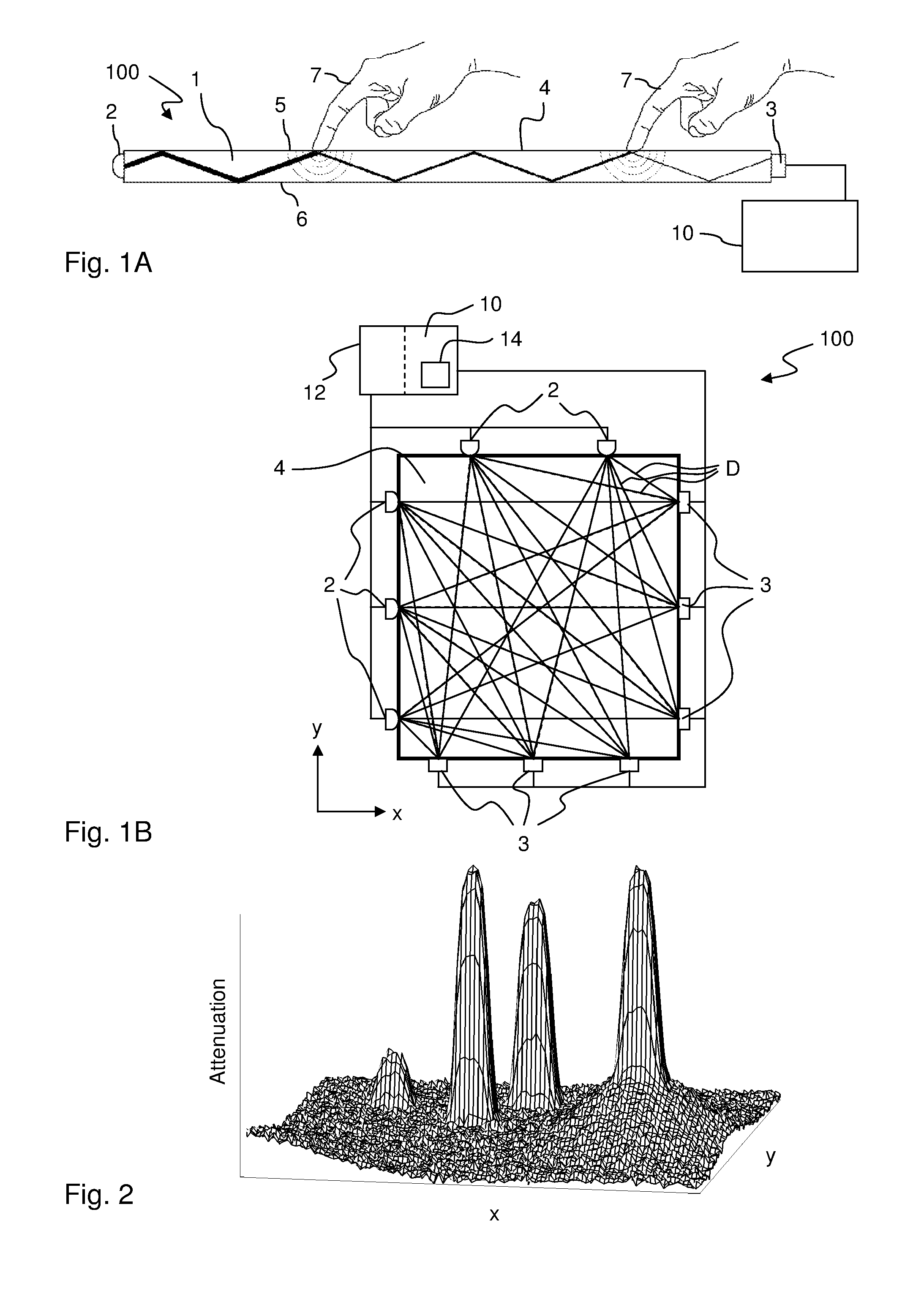
[0035]FIGS. 1A-1B illustrate an example embodiment of a touch-sensitive apparatus 100 that is based on the concept of FUR (Frustrated Total Internal Reflection). The apparatus 100 operates by transmitting light inside a panel 1, from light emitters 2 to light sensors or detectors 3, so as to illuminate a touch surface 4 from within the panel 1. The panel 1 is made of solid material in one or more layers and may have any shape. The panel 1 defines an internal radiation propagation channel, in which light propagates by internal reflections. In the example of FIG. 1, the propagation channel is defined between the boundary surfaces 5, 6 of the panel 1, where the top surface 5 allows the propagating light to interact with touching obj...


PUM


Abstract

A touch-sensitive apparatus is configured to define a touch surface on a panel by propagating diverging energy beams (e.g. of radiation) across the touch surface inside the panel. Two rows (20A, 20B) of components (2, 3) of a first type that emits energy as a diverging beam and a second type that detects energy are functionally connected to the panel at opposite ends of the touch surface. The rows (20A, 20B) are defined by consecutive component blocks (B) that each contain only components (2, 3) of one type and are defined by type and number of included components. Each row (20A, 20B) comprises a respective sequence (S) of two component blocks (B) of different types and is defined by systematically repeating the sequence (S) along the respective opposite end. To achieve an improved spatial resolution of the touch-sensitive apparatus for a given number of components, at least one of the sequences (S) is selected to consist of two component blocks (B) with different number of components, and the sequences (S) are selected such that at least one component block (B) differs between the sequences (S).

Description

CROSS-REFERENCE TO RELATED APPLICATIONS[0001]The present application claims the benefit of Swedish patent application No. 1250519-4, filed 23 May 2012, and U.S. provisional application No. 61 / 650,624, filed 23 May 2012, both of which are incorporated herein by reference.TECHNICAL FIELD[0002]The present invention relates to a touch-sensitive apparatus that operates by propagating energy beams across a touch surface inside a panel.BACKGROUND ART[0003]This type of touch-sensitive apparatus is known in the art. It may be implemented to operate by transmitting light inside a solid light transmissive panel, which defines two parallel boundary surfaces connected by a peripheral edge surface. Light generated by a plurality of emitters is coupled into the panel so as to propagate by total internal reflection (TIR) between the boundary surfaces to a plurality of detectors. The light thereby defines propagation paths across the panel, between pairs of emitters and detectors. The emitters and d...

Claims


Application Information

Patent Timeline
Patent Type & Authority Applications(United States)
IPC IPC(8): G06F3/042
CPCG06F3/0421G06F2203/04109
Inventor WALLANDER, MATS PETTER
Owner FLATFROG LAB
Why Eureka
Try Eureka