
Method and apparatus for relative control of multiple cameras using at least one bias zone

Active Publication Date: 2015-03-26
TRACE OPTICS
View PDF2 Cites 17 Cited by
  • Summary
  • Abstract
  • Description
  • Claims
  • Application Information

AI Technical Summary

Benefits of technology

This patent describes a method for capturing and synchronizing images in a live sports setting. The system uses halo images to deflect players and track their movements. The images are positioned forward of the player and include defending players that may engage them in play. The images have limit lines that give the object or player in the image some space before the edge of the television picture frame. The limit lines have a cushioning effect that enables a smooth visual motion picture without abrupt changes in direction. The computer can determine the camera's field of view by analyzing the pan, tilt, zoom and focus settings. This synchronization allows one human operator to command and control multiple cameras around a designated area and see the camera vision and superimposed geometrical and spatial functions working in real time. The cutting plane is a mathematical plane that allows the captured images to travel across it, enhancing accuracy when tracking motor vehicles. The proportional head room function ensures that the picture frame's height doesn't drop when it reaches a certain height and can zoom in on a player's feet.

Problems solved by technology

The cost of placing a skilled camera operator behind each camera is one of the limitations of the manually controlled systems.
Furthermore due to health and safety issues regarding the operator, the placement of cameras around the perimeter of the playing field is restricted.
A further limitation of a manually controlled system is that camera operators can obscure the action of the sport or stage productions, when close ups are needed as is the case with boxing and ice hockey.
System using tags can however be simplistic, and do not provide for the framing and compositional variables that are required for modern day television broadcasting.
On the other hand one of the problems with master / slave systems is that the images captured by the slaved cameras are the same as those captured by the master camera, the only difference being that the angle from which the image is captured is different for each camera.

Method used


Image

  • Method and apparatus for relative control of multiple cameras using at least one bias zone
  • Method and apparatus for relative control of multiple cameras using at least one bias zone
  • Method and apparatus for relative control of multiple cameras using at least one bias zone

Examples


Embodiment Construction

[0084]There are numerous specific details set forth in the following description. However, from the disclosure, it will be apparent to those skilled in the art that modifications and / or substitutions may be made without departing from the scope and spirit of the invention. In some circumstance specific details may have been omitted so as not to obscure the invention. Similar reference characters indicate corresponding parts throughout the drawings.

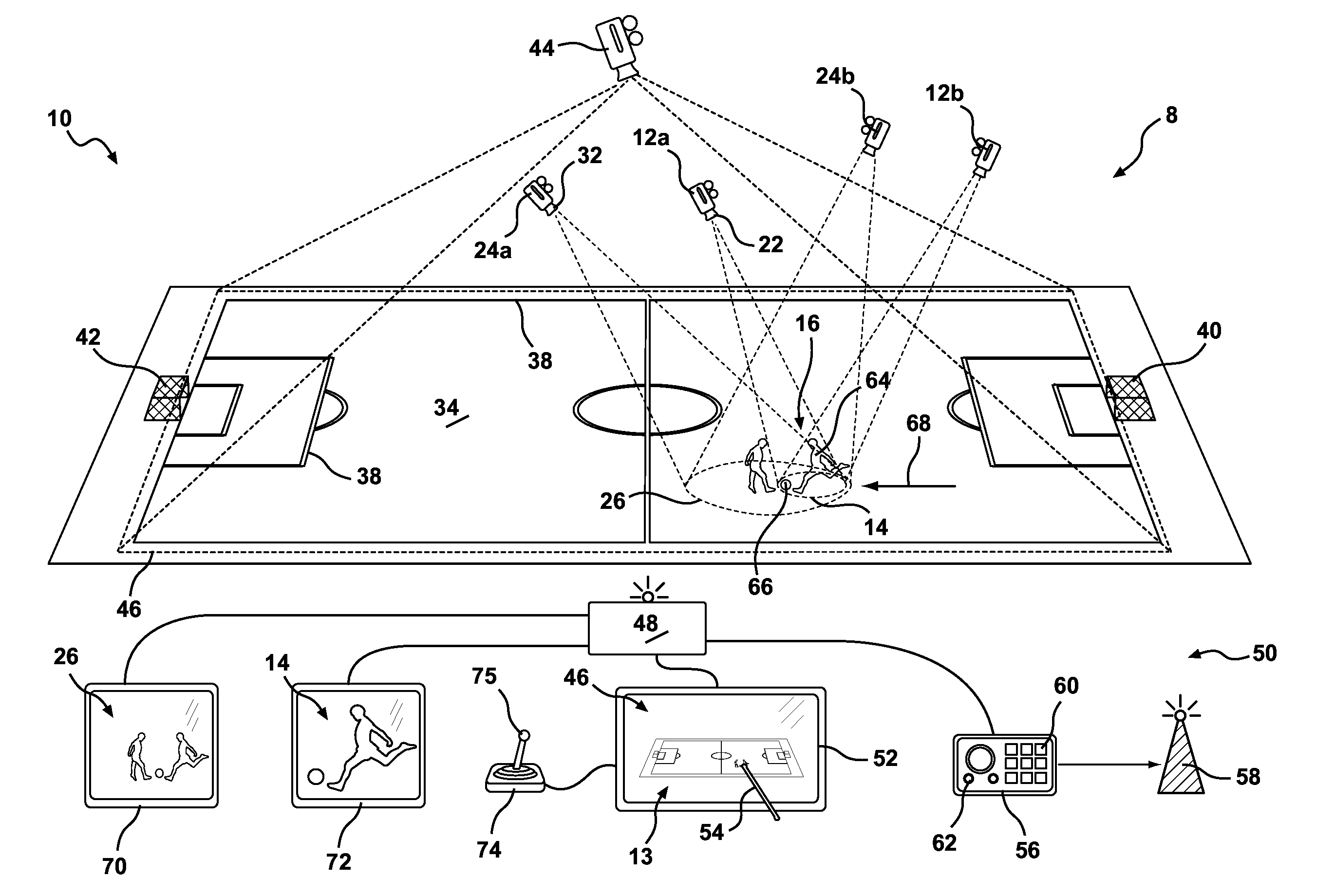
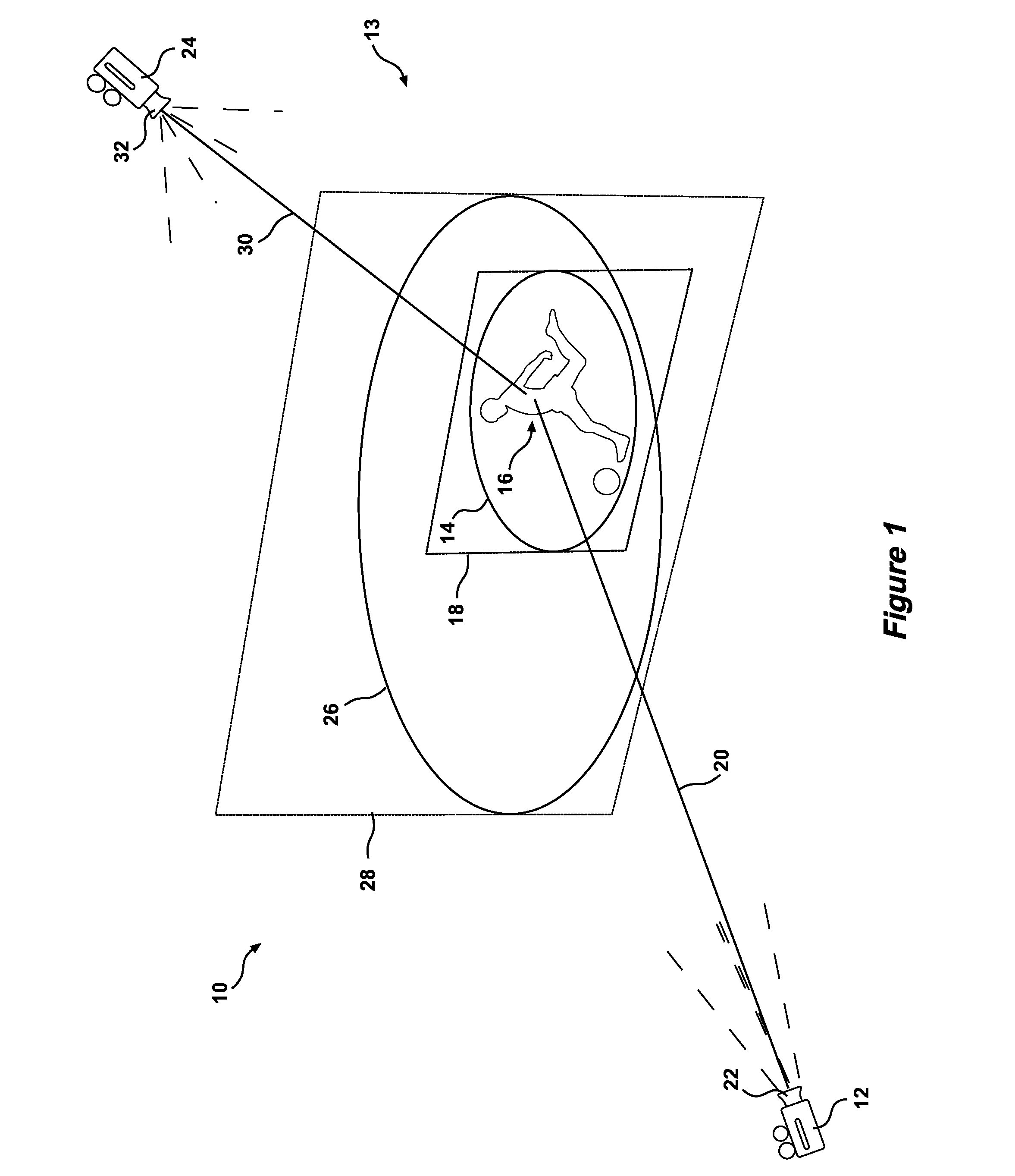
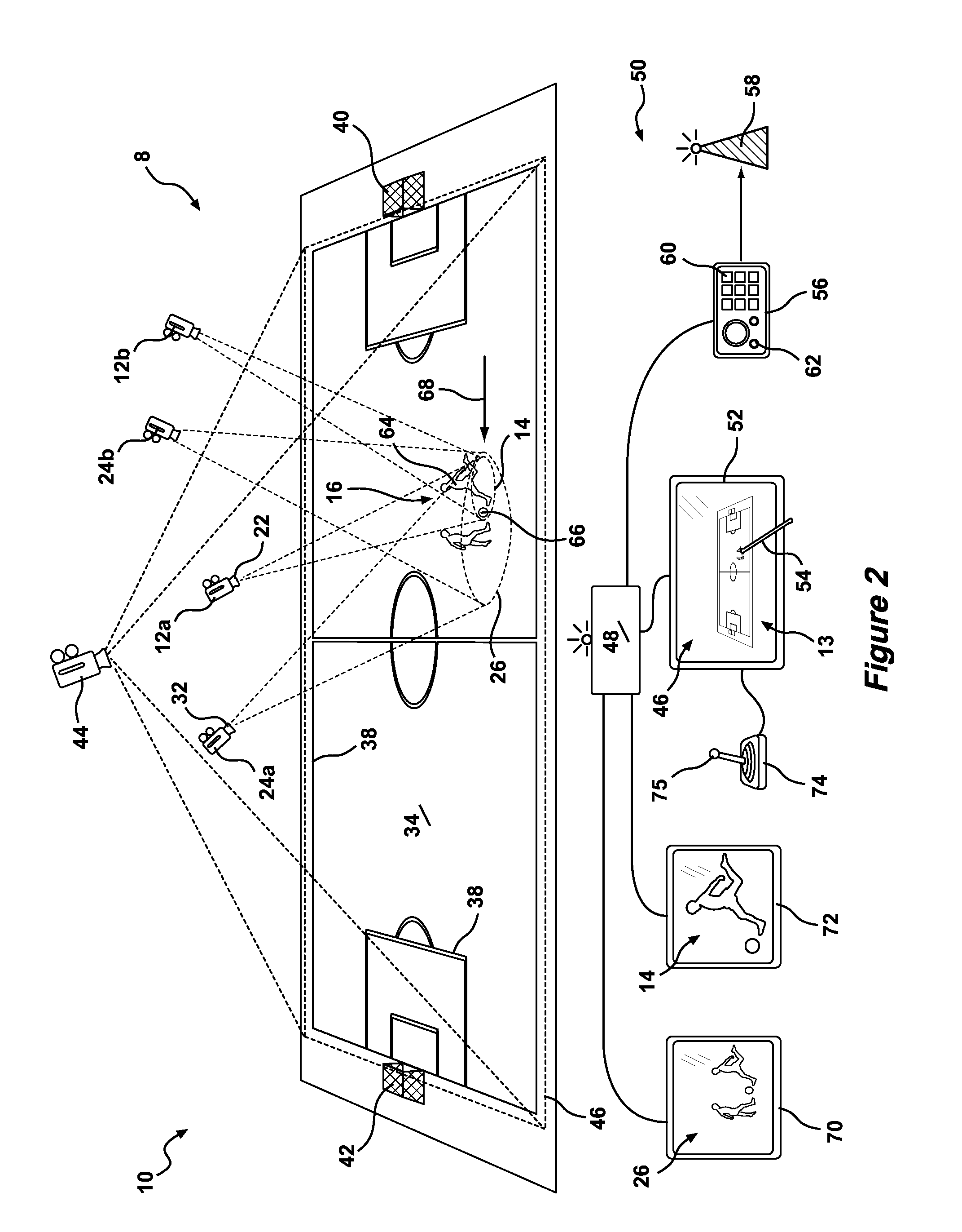
[0085]Referring to the drawings for a more detailed description, a motion picture capturing apparatus 10 is illustrated, demonstrating by way of examples arrangements in which the principles of the present invention may be employed. As illustrated in FIG. 1, the motion picture capturing apparatus includes a first camera 12 for capturing a dynamic primary image 14 of an object 16, the primary image 14 being defined by the field of view 18 and subject distance 20 of the lens 22 of the first camera 12. The apparatus 10 further including a sec...


PUM


Abstract

The present invention relates a method of obtaining motion picture footage of a moving object within an environment, being a surveyed environment or an environment of known dimensions. The method including the steps of: creating a computer generated virtual map of the environment within a control apparatus. At least one bias zone overlays the virtual map, the at least one bias zone being a predetermined or variable pattern, capturing a dynamic primary image of said object using a first motion picture camera, and capturing a dynamic halo image that extends around the primary image using a second motion picture camera. The said first and second motion picture cameras being controlled by the control apparatus such that a position or size of the halo image relative to the primary image is regulated by the at least one bias zone.

Description

RELATED U.S. APPLICATION[0001]This application is a continuation-in-part of U.S. application Ser. No. 13 / 392,515 filed Feb. 24, 2012, entitled, METHOD AND APPARATUS FOR RELATIVE CONTROL OF MULTIPLE CAMERAS, pending, the content of which is incorporated herein by reference, which is a US national stage entry of PCT / AU2010 / 000886 filed Jul. 13, 2010, under the International Convention, which claimed priority over Australian Patent Application No. 2009904169 filed Aug. 31, 2009.FIELD OF THE INVENTION[0002]The present invention relates generally to the field of camera control systems and in one aspect relates to the control of at least two cameras for capturing different images of an object moving across a surface wherein a primary image is contained, and movable within, a halo image, the position of the halo image being dependent upon the movement of the object and controlled by at least one bias zone overlaying a computer generated virtual map of the present invention.[0003]The reader...

Claims


Application Information

Patent Timeline
IPC IPC(8): H04N5/232H04N7/18H04N5/247
CPCH04N5/23216H04N7/185H04N5/247H04N7/181H04N23/62H04N23/90
Inventor ANDERSON, JEREMY LORENZ
Owner TRACE OPTICS
Features
  • Generate Ideas
  • Intellectual Property
  • Life Sciences
  • Materials
  • Tech Scout
  • Unparalleled Data Quality
  • Higher Quality Content
  • 60% Fewer Hallucinations
Learn More