Motorized drive for mobile fluoroscopy units

a technology of motorized drive and mobile fluoroscopy, which is applied in the direction of electrical equipment, medical science, diagnostics, etc., can solve the problem of becoming difficult to integrate a prior art sliding collar mobile c-arm into a surgical navigation system

Inactive Publication Date: 2015-03-26
GRADY JOHN K
View PDF2 Cites 12 Cited by
  • Summary
  • Abstract
  • Description
  • Claims
  • Application Information

AI Technical Summary

Benefits of technology

[0021]It is also necessary to consider coordinated turns of the mobile fluoroscopy unit while being transported within the hospital. With the present invention, independent steering positioning servos for all the vectored wheels allows computer coordination of each wheel angle to the desired turn radius.

Problems solved by technology

As a result, it becomes difficult to integrate a prior art “sliding collar” mobile C-arm into a surgical navigation system.

Method used


Image

  • Motorized drive for mobile fluoroscopy units
  • Motorized drive for mobile fluoroscopy units
  • Motorized drive for mobile fluoroscopy units

Examples


Embodiment Construction

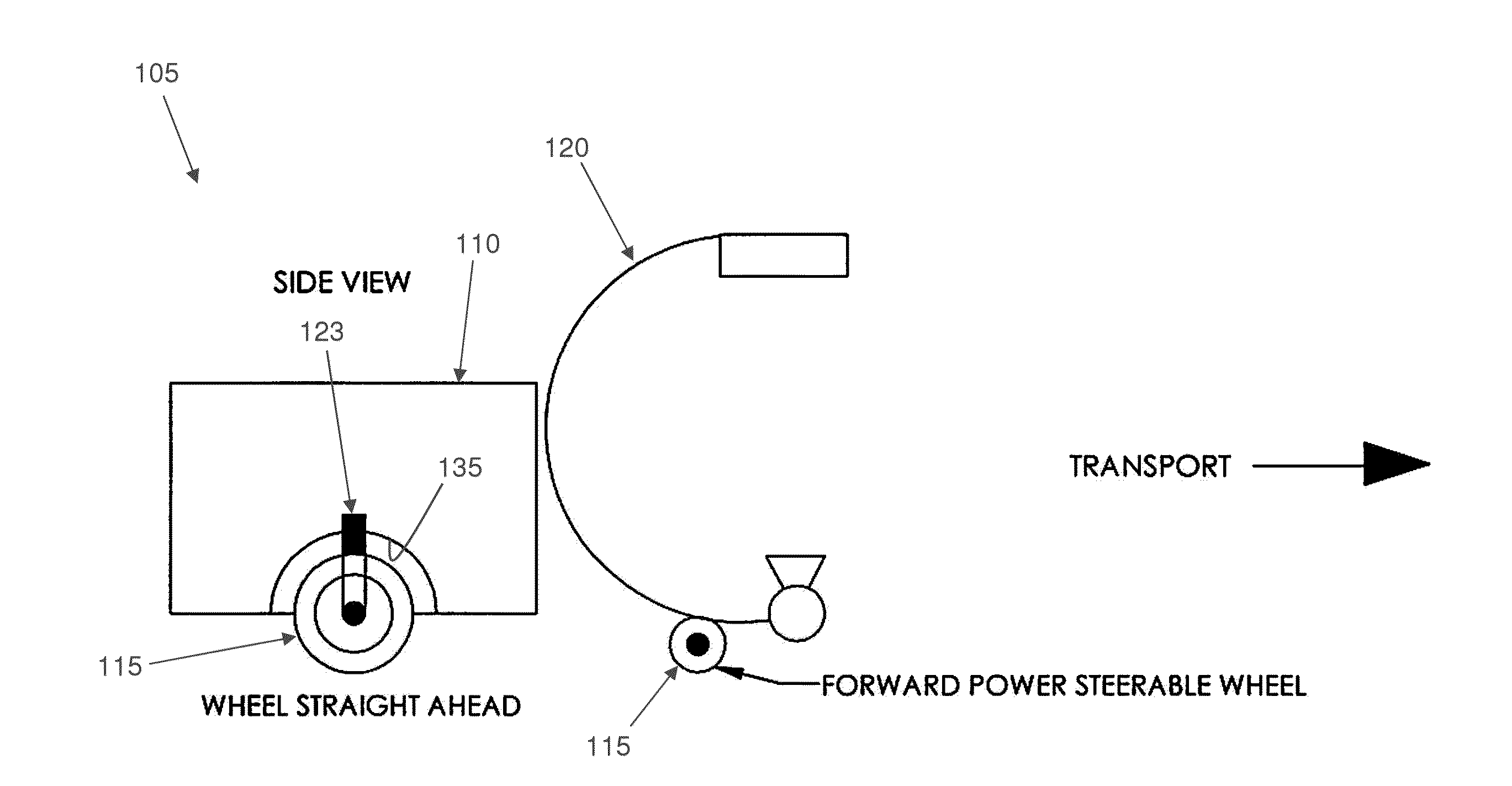
[0032]Looking now at FIGS. 3-6, the present invention comprises a mobile fluoroscopy unit 105 having a base 110, at least two powered wheels 115 for moving base 110 relative to the floor, and a C-arm 120 cantilevered relative to base 110. In accordance with the present invention, each of the at least two powered wheels 115 is configured to be rotated about a vertical axis 123 (e.g., via a vertical rotation mechanism 124) such that each of the at least two powered wheels 115 is directable in any direction. Each of the powered wheels 115 is configured to be rotated about a horizontal axis 124A (e.g., via a horizontal rotation mechanism 124B) such that each of the at least two powered wheels 115 can be driven in a given direction. A steering input 125 (e.g., a vertical or steering axis, such as a joystick or wheel) may be used to selectively aim powered wheels 115 in any arbitrary, or vector, direction. In one preferred form of the present invention, steering input 125 further comprise...


PUM


Abstract

A mobile C-arm fluoroscopy unit comprising a self-contained radial coordinate or vector movement mechanism utilizing at least one motor-driven wheel, wherein the at least one motor-driven wheel is individually continuously steerable around a generally vertical steering axis.

Description

REFERENCE TO PENDING PRIOR PATENT APPLICATION[0001]This patent application claims benefit of pending prior U.S. Provisional Patent Application Ser. No. 61 / 880,213, filed Sep. 20, 2013 by John K. Grady for MOTORIZED DRIVE FOR MOBILE FLUOROSCOPY UNITS (Attorney's Docket No. GRADY-1 PROV), which patent application is hereby incorporated herein by reference.FIELD OF THE INVENTION[0002]The present invention relates generally to precision operator control and setting of the location of the center of a mobile X-ray unit beam, such as where X-ray fluoroscopy is used in the operating room on mobile or “portable” self-contained fluoro or C-arm units, particularly in the “Digital OR” or surgical navigation environment.BACKGROUND OF THE INVENTION[0003]Prior approaches to X-ray positioning of mobile C-arms have required the use of a second carriage or “X” motion element mounted on the wheeled unit base to provide one axis of an X-Y system, the wheels on the floor providing the other or “Y” axis ...

Claims


Application Information

Patent Timeline
Patent Type & Authority Applications(United States)
IPC IPC(8): A61B6/00
CPCA61B6/4405A61B6/487A61B6/4441
Inventor GRADY, JOHN K.
Owner GRADY JOHN K
Why Eureka
Try Eureka