Separating device

a technology of separating device and support element, which is applied in the direction of threshers, applications, agriculture tools and machines, etc., can solve the problems of high wear on the sharp edge of the front edge of the ramp-shaped support element, and the grates are exposed to a high degree of abrasion, so as to reduce the risk of crop damage, and increase the wear resistance

Active Publication Date: 2015-03-26
CLAAS SELBSTFAHRENDE ERNTEMASCHINEN GMBH
View PDF4 Cites 5 Cited by
  • Summary
  • Abstract
  • Description
  • Claims
  • Application Information

AI Technical Summary

Benefits of technology

[0009]Preferably, the course of the front edge can be convex. It is thereby possible to achieve a gentle deflection of crop in the region of the front edge. In contrast thereto, a concavely embodied front edge could result in a hollowing-out of the crop-treatment element, which would result in greater wear.
[0010]Advantageously, the front edge is provided, at least in sections, with a coating in order to increase the wear-resistance. The service life of the crop-treatment element is additionally increased as a result. The resistance o

Problems solved by technology

The grates are directly engaged with the crop, which exerts a highly abrasive effect on the grates.
The wear that occurs on the sharp-

Method used


Image

  • Separating device
  • Separating device
  • Separating device

Examples


Embodiment Construction

[0024]The following is a detailed description of example embodiments of the invention depicted in the accompanying drawings. The example embodiments are presented in such detail as to clearly communicate the invention and are designed to make such embodiments obvious to a person of ordinary skill in the art. However, the amount of detail offered is not intended to limit the anticipated variations of embodiments; on the contrary, the intention is to cover all modifications, equivalents, and alternatives falling within the spirit and scope of the present invention, as defined by the appended claims.

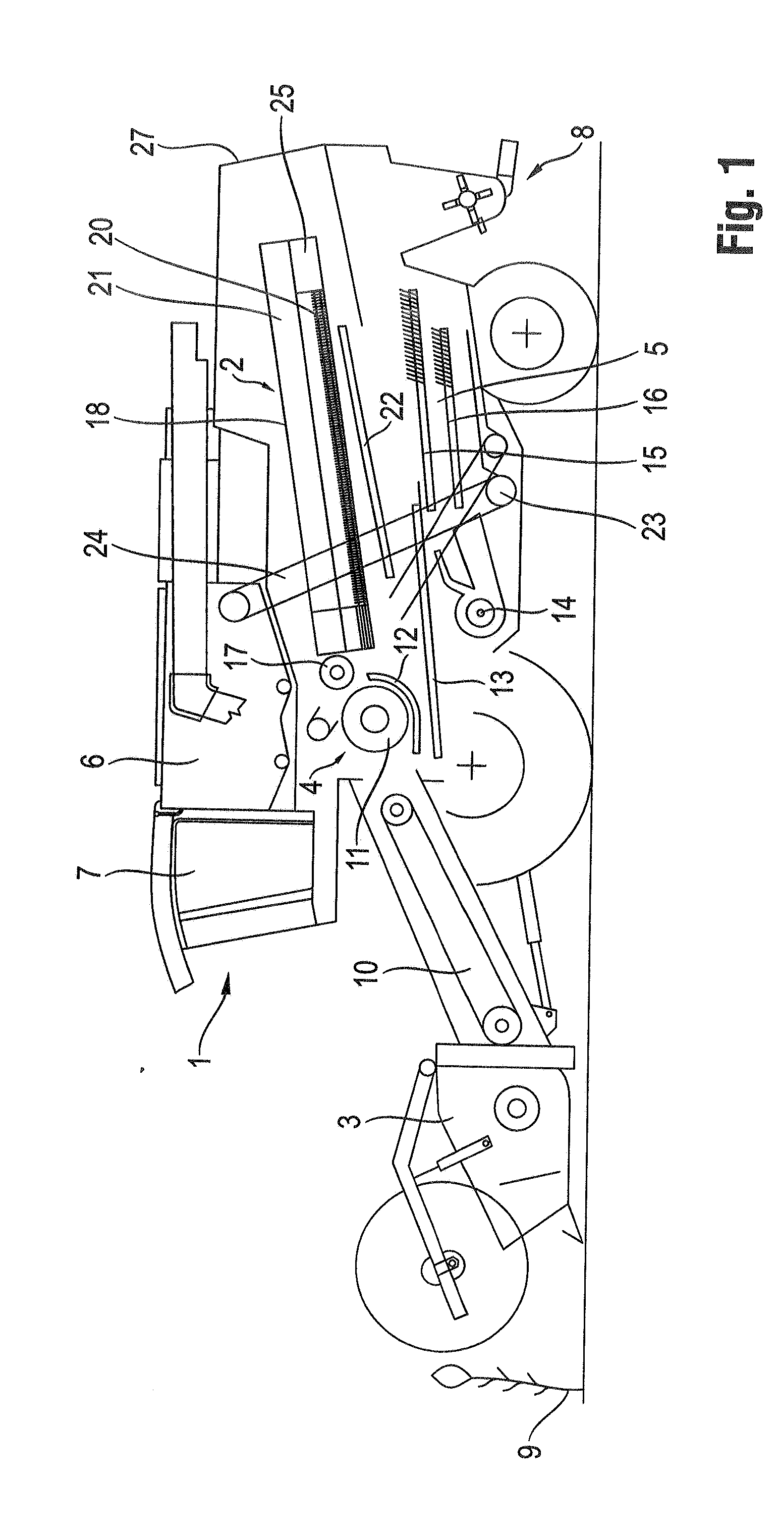
[0025]The combine harvester 1 depicted schematically in FIG. 1 comprises an axial separator 2, a header 3, a threshing unit 4, a cleaning unit 5, a grain tank 6, a driver's cab 7 and a further-handling device 8 for the residual crop flow, which is disposed downstream of the axial separator 2, and a straw chopper and / or a spreader

[0026]The crop 9 cut by the header 3 travels through a feeder ...


PUM


Abstract

A separating device formed with rotationally driven components and stationary components has at least one crop-treatment element for processing crop. The crop-treatment element extends transversely to the rotational direction (R) of the components, at least in sections. The crop-treatment element has a substantially cuboid cross-section and a front edge with a curved course optimized in terms of flow, and which faces a rotational direction (R) and away from a conveyance direction (FR) of the crop.

Description

CROSS-REFERENCE TO A RELATED APPLICATION[0001]The invention described and claimed hereinbelow is also described in German Patent Application DE 10 2013 110452A, filed on Sep. 24, 2013. The German Patent Application, the subject matters of which is incorporated herein by reference, provides the basis for a claim of priority of invention under 35 U.S.C. 119(a)-(d).BACKGROUND OF THE INVENTION[0002]The present invention relates to a separating device. Known separating devices can be designed as axial separating rotors of a combine harvester, which are used to separate crop picked up by the combine harvester into the different components thereof, and to separate and remove said components. The crop is separated by the separating device into a grain component and a non-grain component, such as straw and chaff, by a treatment process, which physically acts on the crop.[0003]Document EP 2 298 063 A2 makes known a separating device, which is designed as an axial threshing-separating rotor. T...

Claims


Application Information

Patent Timeline
IPC IPC(8): A01F7/02
CPCA01F7/02A01F7/067A01F12/20A01F12/22A01F12/24A01F12/26
Inventor HOLTMANN, BERNDPELLMANN, MARKUS
Owner CLAAS SELBSTFAHRENDE ERNTEMASCHINEN GMBH
Why Eureka
Try Eureka