
Surgical implant device and surgical implant insertion assembly for the translation and fusion of a facet joint of the spine

a technology of surgical implants and insertion assemblies, which is applied in the field of spinal stenosis surgery and surgical implant devices, can solve the problems of inadequate treatment of significant shortcomings in devices and methodologies, and inability to adequately address surgeon concerns and patient symptoms, so as to improve the size of the foramen, promote the fusion of superior and inferior facets, and alleviate a given physical ailment or condition

Active Publication Date: 2015-03-26
MINSURG INT INC
View PDF9 Cites 9 Cited by
  • Summary
  • Abstract
  • Description
  • Claims
  • Application Information

AI Technical Summary

Benefits of technology

The invention aims to address the issues of stenosis (narrowing of the spinal canal) which causes pain and neuropathy in the lower body, as well as degenerative disc disease and spinal stenosis. By displacing the spinal nerves, the invention increases the size of the foramen (the space where nerves exit the spine) and stretches out the ligamentum flavum (the redundant tissue that connects spinal segments) which can help to unload the spine and reduce pain.

Problems solved by technology

These conventional devices and methodologies, however, suffer from a number of significant shortcomings and often fail to adequately address surgeon concerns and patient symptoms.

Method used


Image

  • Surgical implant device and surgical implant insertion assembly for the translation and fusion of a facet joint of the spine
  • Surgical implant device and surgical implant insertion assembly for the translation and fusion of a facet joint of the spine
  • Surgical implant device and surgical implant insertion assembly for the translation and fusion of a facet joint of the spine

Examples


Embodiment Construction

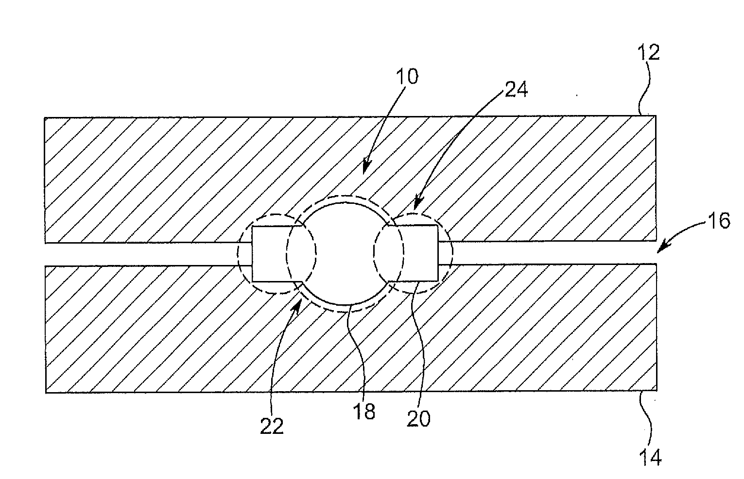
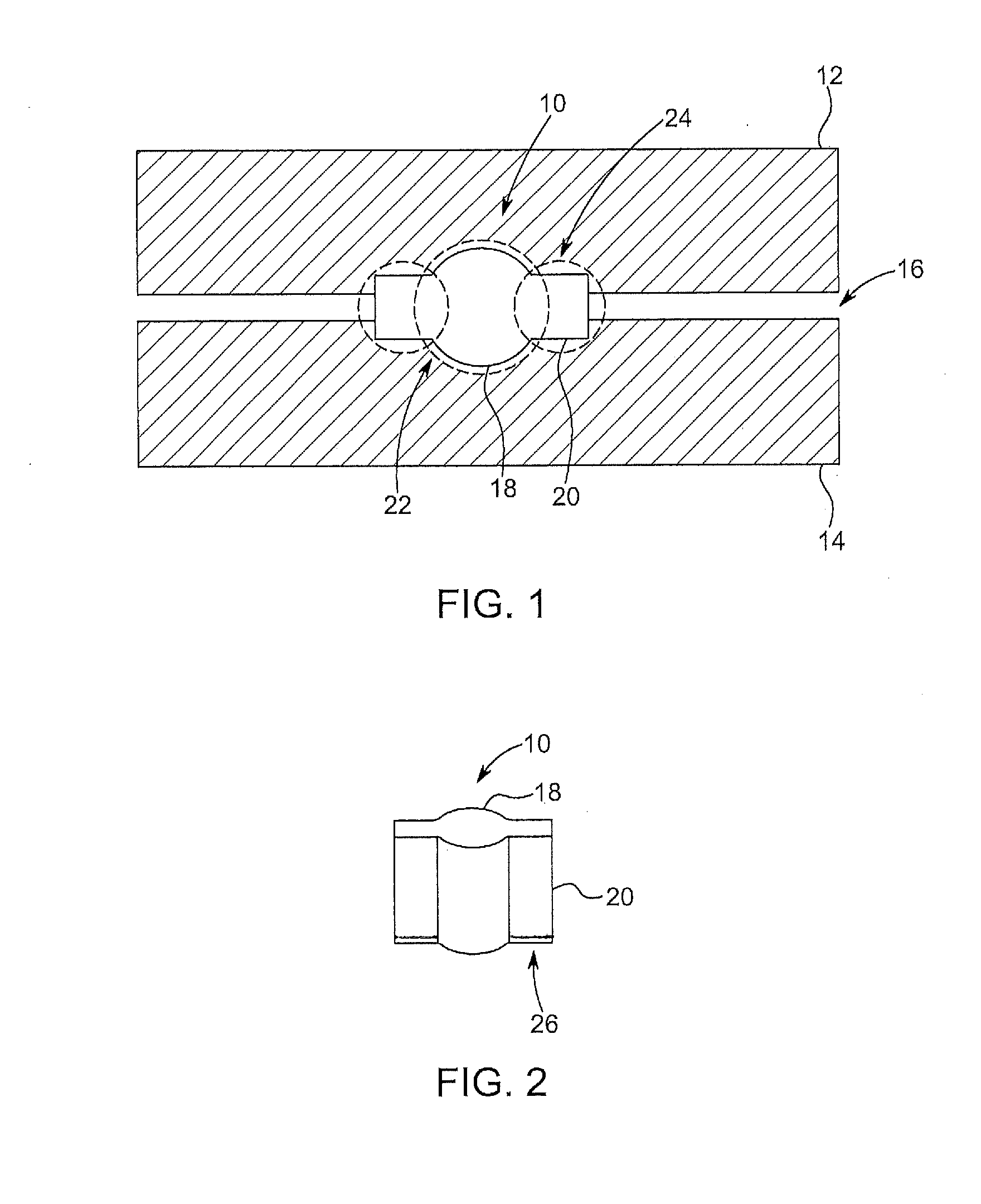
[0031]Referring now specifically to FIG. 1, in one exemplary embodiment of the present invention, the surgical implant device 10 is disposed generally between the superior facet 12 and the inferior facet 14 of the facet joint 16 of the spine. The surgical implant device 10 includes a body portion 18 that has a substantially circular cross-sectional shape and a pair of protruding side portions 20 each having a substantially rectangular shape that extend radially from the body portion 18. It will be readily apparent to those of ordinary skill in the art that any number of protruding side portions 20 may be used and that each may have another suitable shape. In use, the body portion 18 is disposed, or press fit, within a central hole 22 drilled in and between the superior facet 12 and the inferior facet 14; the body portion 18 breaking the plane of the associated articulating surfaces. Each of the protruding side portions 20 is disposed, or press fit, within a side hole 24 drilled in a...


PUM


Abstract

A surgical implant device configured to be implanted in a facet joint of a spine, comprising: a substantially cylindrical central body portion; and a pair of substantially prismatic side portions extending in radially opposite directions disposed on either side of the substantially cylindrical central body portion; wherein the substantially cylindrical central body portion is configured to be disposed in a central hole formed across the facet joint and crossing a plane of an articulating surface of each of a superior facet and an inferior facet thereof; wherein each of the substantially prismatic side portions is configured to be disposed in a side hole parallel to the central hole formed across the facet joint and crossing the plane of the articulating surface of each of the superior facet and the inferior facet thereof; and wherein each of the side holes partially overlap the central hole.

Description

CROSS-REFERENCE TO RELATED APPLICATION(S)[0001]The present patent application / patent is a continuation-in-part of co-pending U.S. patent application Ser. No. 13 / 276,058, filed on Oct. 18, 2011, and entitled “SURGICAL IMPLANT DEVICE FOR THE TRANSLATION AND FUSION OF A FACET JOINT OF THE SPINE,” which is a continuation-in-part of U.S. patent application Ser. No. 12 / 875,374 (U.S. Pat. No. 8,814,907), filed on Sep. 3, 2010 (issued on Aug. 26, 2014), and entitled “SURGICAL IMPLANT DEVICE FOR THE TRANSLATION AND FUSION OF A FACET JOINT OF THE SPINE,” which claims the benefit of priority of U.S. Provisional Patent Application No. 61 / 239,594, filed on Sep. 3, 2009, and entitled “SURGICAL IMPLANT DEVICE FOR THE TRANSLATION AND FUSION OF A FACET JOINT OF THE SPINE,” the contents of all of which are incorporated in full by reference herein.FIELD OF THE INVENTION[0002]The present invention relates generally to a novel surgical implant device and surgical implant insertion assembly for treating ...

Claims


Application Information

Patent Timeline
Patent Type & Authority Applications(United States)
IPC IPC(8): A61B17/70A61B17/88A61B17/02
CPCA61B17/7064A61B2017/0256A61B17/8866A61B17/025
Inventor LINS, ROBERT E.
Owner MINSURG INT INC
Learn More