Vigilance Monitoring System

a monitoring system and driver technology, applied in diagnostics, medical science, computation using non-denominational number representations, etc., can solve problems such as harmful social or economic consequences, lack of operator vigilance, etc., and achieve the effect of accurately detecting the driver's state of vigilan

Inactive Publication Date: 2015-03-26
COMPUMEDICS
View PDF1 Cites 28 Cited by
  • Summary
  • Abstract
  • Description
  • Claims
  • Application Information

AI Technical Summary

Benefits of technology

[0072]It is desirable to ensure that the driver response tests are not anticipated by the driver to more accurately detect the driver's state of vigilance. It is of course also important that the selected method of testing driver response, does not in any way distract the driver or contribute to the driver's lapse in concentration.
[0073]The system may be buil

Problems solved by technology

A typical application may include monitoring the driver of a vehicle or pilot of an aircraft, although the invention also has applications in areas involving related occupations such as

Method used


Image

  • Vigilance Monitoring System
  • Vigilance Monitoring System
  • Vigilance Monitoring System

Examples


Embodiment Construction

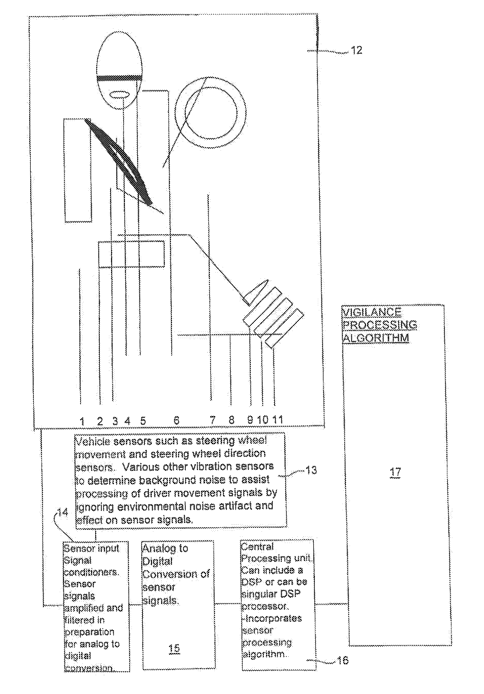
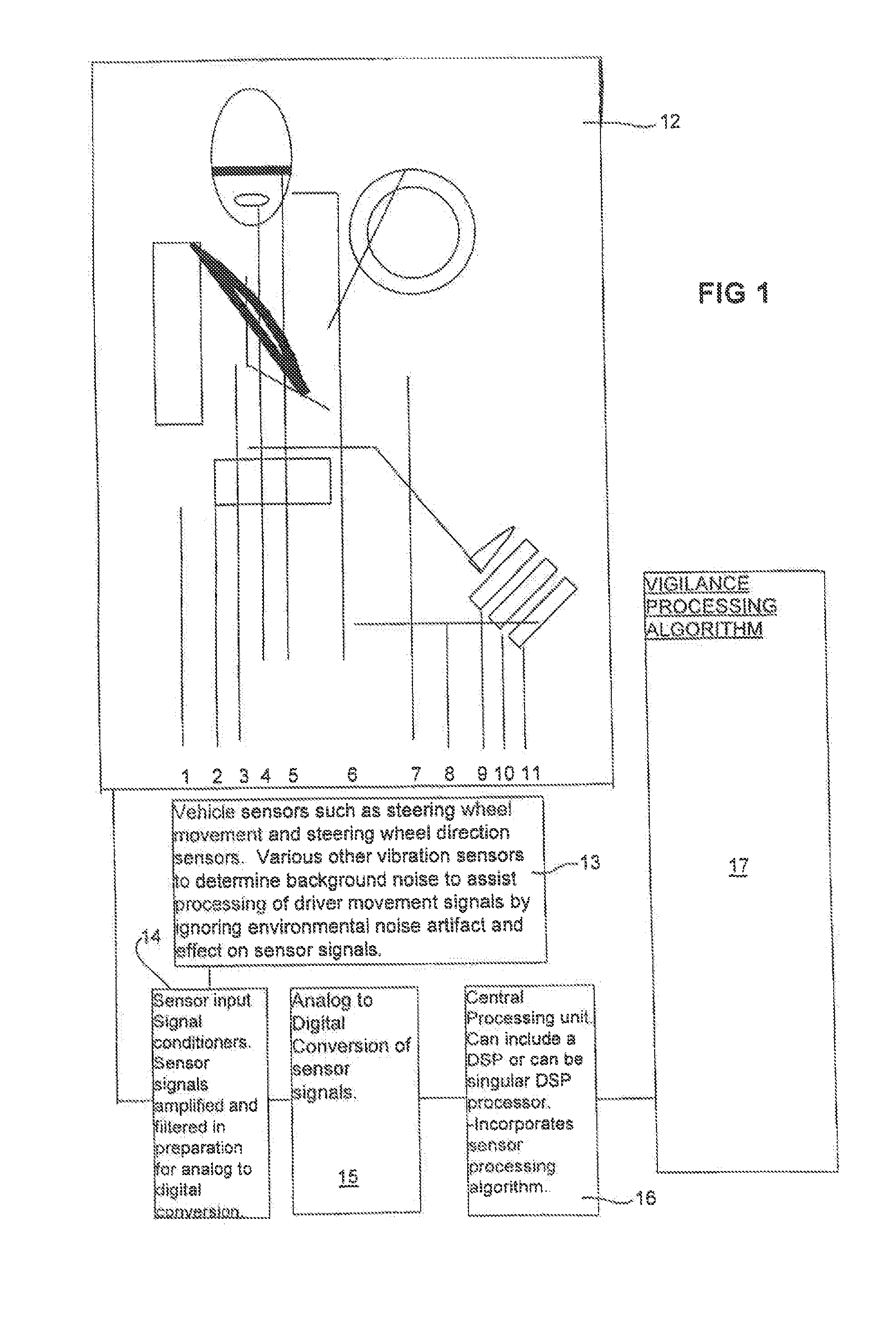
[0100]Referring to FIG. 1, block 12 shows a plurality of sensors 1 to 11 associated with a vehicle and driver. The or each sensor may include piezoelectric or electrostatic material such as CSD or PVDF material. The material can be divided into plural sections of the driver's seat, for example. The various sensors are summarized below.

[0101]1. Upper Driver Seat Sensor

[0102]Drivers seat top edge of upper section

[0103]Drivers seat centre of upper section

[0104]Drivers seat base of upper section

[0105]2. Lower Driver Seat Sensor

[0106]Drivers seat front edge of lower section

[0107]Drivers seat centre of lower section

[0108]Drivers seat rear of lower section

[0109]3. Driver Seat-Belt Sensor

[0110]Driver's seat-belt upper section

[0111]Driver's seat-belt lower section

[0112]4. Driver's Head Tilt Per Driver Cap or Similar Sensor

[0113]The driver's head tilt per driver cap or a device to clip over drivers ear or as part of driving goggles or glasses. These sensors can be, for example, positional swi...


PUM


Abstract

The present invention pertains to a system and method of monitoring the alertness or wakefulness of a driver. The monitored parameters include cardiac, respiratory and movement parameters. Sensors are located in various locations of the driver side section to detect the vigilance of a driver. These sensors include pressure sensors embedded in the seat and pedals, and a head band for monitoring EEG, EMG and EOG signals.

Description

RELATED APPLICATIONS[0001]This application is a continuation of U.S. patent application Ser. No. 13 / 351,857, filed Jan. 17, 2012, which is a continuation of U.S. patent application Ser. No. 10 / 417,247, filed Apr. 15, 2003, now U.S. Pat. No. 8,096,946, which is a continuation of U.S. patent application Ser. No. 09 / 890,324, filed Jul. 26, 2001, now U.S. Pat. No. 6,575,902, which was a national stage application under 35 U.S.C. §371 of International Application No. PCT / AU99 / 01166, filed Dec. 24, 1999, which claimed priority from Australian applications PP 8325, filed Jan. 27, 1999, and PQ 3740, filed Oct. 29, 1999, which applications are all hereby incorporated by reference in their entireties.SUMMARY OF THE INVENTION[0002]The present invention relates to a vigilance monitoring system. In particular the invention relates to a system for monitoring, recording and / or analyzing vigilance, alertness or wakefulness and / or a stressed state of an operator of equipment or machinery in a variet...

Claims


Application Information

Patent Timeline
IPC IPC(8): B60W40/08B60T7/12A61B5/18A61B3/113A61B5/0476A61B5/0496B60K28/02B60K28/06B60L3/02B60T7/14G08B21/06
CPCB60W40/08B60W2040/0872B60T7/12A61B5/18A61B3/113A61M21/02A61M2021/0044A61M2021/0083A61M2230/10A61M2230/14A61M2230/60B60L3/02B60L2260/46B60T7/14G08B21/06A61B5/7232B60L2200/26A61B5/398A61B5/369
Inventor BURTON, DAVID
Owner COMPUMEDICS
Why Eureka
Try Eureka