Device for determining a filling level

Active Publication Date: 2015-04-02
HELLA KG HUECK & CO
View PDF2 Cites 8 Cited by
  • Summary
  • Abstract
  • Description
  • Claims
  • Application Information

AI Technical Summary

Benefits of technology

[0015]In another preferred design of the invention the measuring section is shaped like a truncated cone at its foot. This is the reason why bubbles cannot collect in, or adhere to, the region of the foot of the measuring section, nor at the transition between meas

Problems solved by technology

When the engine is running however, in particular in a motor vehicle, it is very difficult, if not impossible to determine the f

Method used


Image

  • Device for determining a filling level
  • Device for determining a filling level
  • Device for determining a filling level

Examples


Embodiment Construction

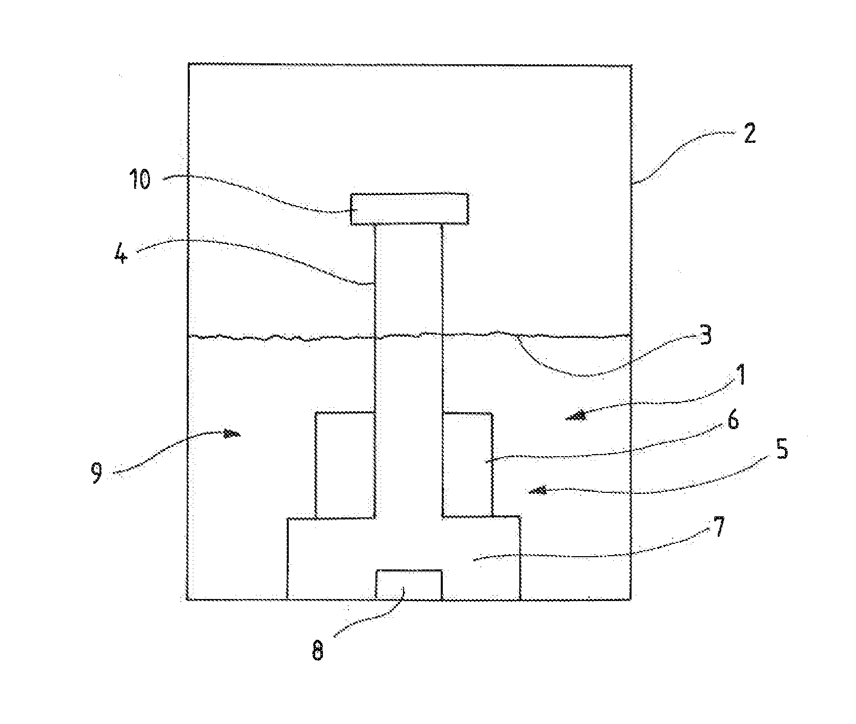
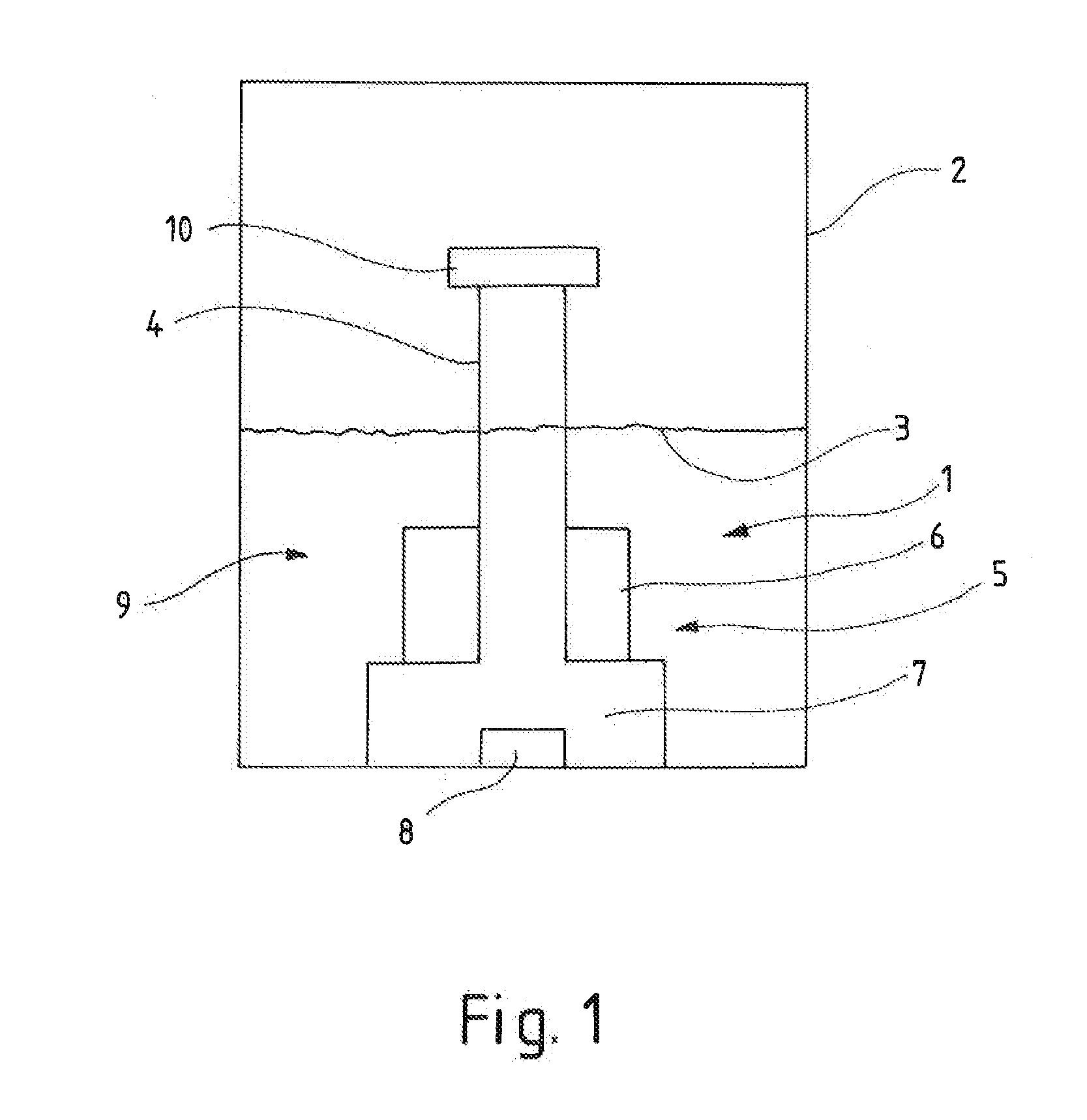
[0023]FIG. 1 represents a principal view of the elements of the device 1 according to the invention. The device 1 according to the invention is arranged in a container 2 for measuring the filling level 3 of a liquid in this container 2. The device 1 comprises an antechamber 5 which here consists of a first antechamber 6 and a second antechamber 7. An ultrasound converter 7 is arranged in the antechamber 5, here in the second antechamber 7, and this converter is arranged below a measuring section 4 extending vertically upwards and emits ultrasound waves in upward direction, which are reflected at the boundary surface formed by the filling level 3 between liquid and gas. Number 9 denotes a damping cup which here represents the essential part of the device 1. The damping cup 9 has a cap 10 fitted to it which closes the damping cup 9 at the top and which comprises a vent 12.

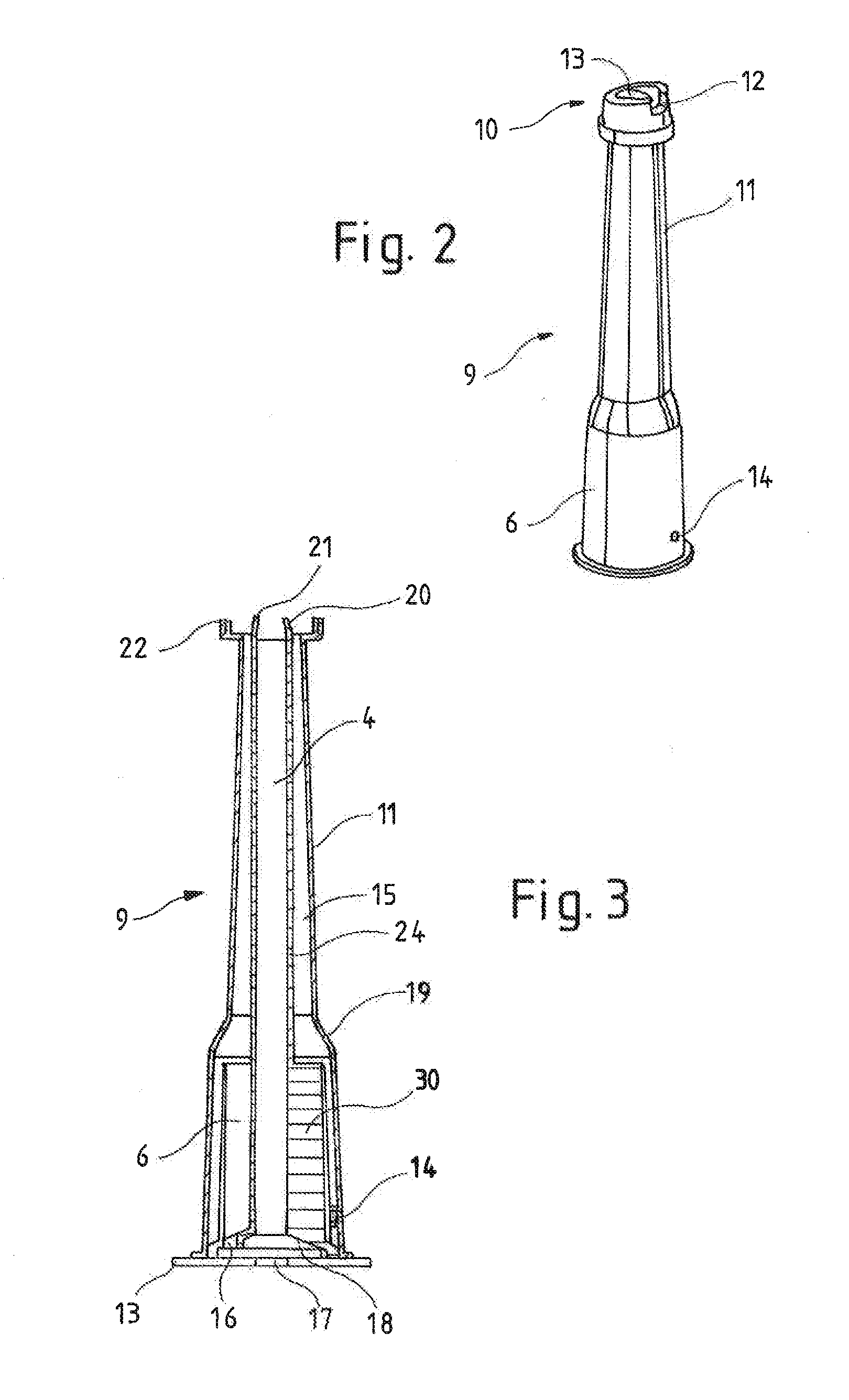
[0024]In FIG. 2 the damping cup 9 is shown in a perspective view. The second antechamber 7 is not shown here, but ...


PUM


Abstract

A device for determining a filling level of a container is provided, having a damping cup, a measuring section extending vertically inside the damping cup, and having an ultrasound converter arranged at its lower end region, and at least one antechamber. A calming structure is arranged in at least a part of at least one antechamber, to achieve as much degassing of the liquid as possible. The part of the antechamber having the calming structure is designed to be open towards the top over a large area and is connected, via a venting channel, with a vent in the upper region of the device.

Description

BACKGROUND OF THE INVENTION[0001]1. Field of the Invention[0002]The invention relates to a device for determining a filling level of a container, comprising a damping cup, a measuring section extending vertically inside the damping cup and having an ultrasound converter arranged at its lower end region, and at least one antechamber, wherein a calming structure is arranged in at least a part of at least one antechamber.[0003]2. Brief Description of the Related Art[0004]Devices of this kind are known for example from the DE 10 2010 011 492 A1 and the DE 10 2008 027 969 A1. Oil levels in engines are usually checked using ultrasound sensors. These emit sound waves which are reflected at the boundary surface between two media such as air and oil (wherein instead of oil other liquids can also be measured) and received again by the ultrasound sensor. The filling level in the container which comprises the device, can be determined from the recorded travelling time of the sound waves. When t...

Claims


Application Information

Patent Timeline
IPC IPC(8): F01M11/12G01F23/296
CPCG01F23/2962F01M11/12F01M11/06F02D1/00G01F23/0046B60K2015/03217
Inventor NIEMANN, THOMASPALLOKS, JURGEN
Owner HELLA KG HUECK & CO
Why Eureka
Try Eureka