
Spot welding apparatus

Active Publication Date: 2015-04-02
HYUNDAI MOTOR CO LTD
View PDF14 Cites 6 Cited by
  • Summary
  • Abstract
  • Description
  • Claims
  • Application Information

AI Technical Summary

Benefits of technology

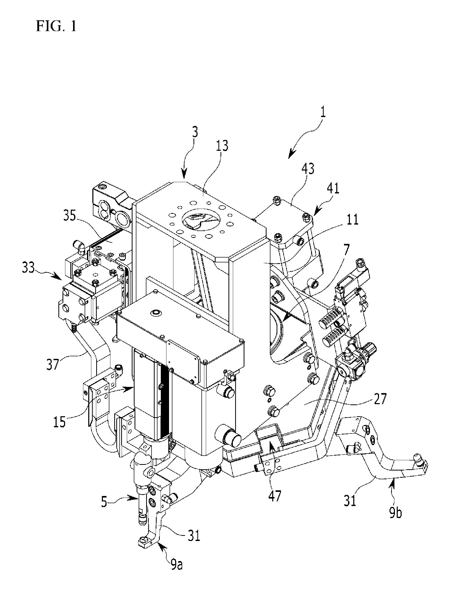
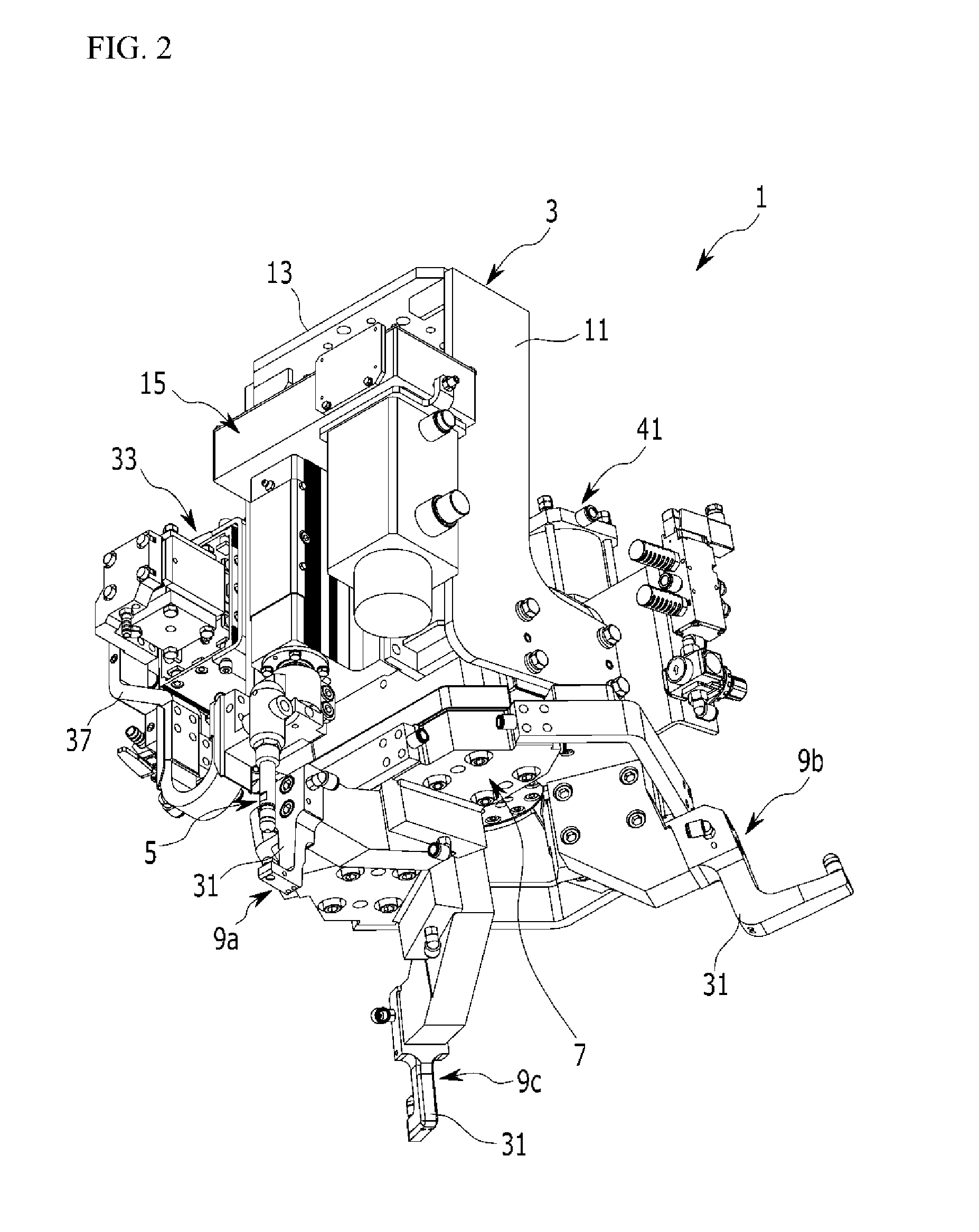
The present invention provides a spot welding apparatus that can be used on multiple vehicle types and welding points, without the need for multiple robots. The apparatus has lower welding guns that automatically select the relevant guns for a specific welding point, improving productivity, flexibility, and efficiency of the vehicle body process. The apparatus can perform a welding operation quickly in a limited space, increasing productivity and flexibility. It also reduces installation costs by using a single apparatus for multiple vehicle types and welding points.

Problems solved by technology

However, in the related art spot welding operation, since a single spot welding apparatus per robot is installed in a robot arm, only single spotting welding is performed at every moment the arm of the robot moves, requiring a great amount of time to perform a prescribed number of welding point operations to degrade productivity and efficiency.
In addition, lower welding guns each having a different shape should be applied according to positions and shapes of welding points, increasing investment cost for facilities, and in particular, in a case in which a plurality of robots having a spot welding apparatus employing a lower welding gun having a special shape are in use, facility and maintenance cost is increased, energy is excessively used, and space occupancy of robots in a mass-production line is increased.

Method used


Image

  • Spot welding apparatus
  • Spot welding apparatus
  • Spot welding apparatus

Examples


Embodiment Construction

[0044]Reference will now be made in detail to various embodiments of the present invention(s), examples of which are illustrated in the accompanying drawings and described below. While the invention(s) will be described in conjunction with exemplary embodiments, it will be understood that present description is not intended to limit the invention(s) to those exemplary embodiments. On the contrary, the invention(s) is / are intended to cover not only the exemplary embodiments, but also various alternatives, modifications, equivalents and other embodiments, which may be included within the spirit and scope of the invention as defined by the appended claims.

[0045]In the drawings, sizes and thickness of components are arbitrarily shown for the description purposes, so the present invention is not limited to the illustrations of the drawings and thicknesses are exaggerated to clearly express various parts and regions.

[0046]To clarify the present invention, portions irrespective of descript...


PUM

PropertyMeasurementUnit
Angleaaaaaaaaaa
Pressureaaaaaaaaaa
Angleaaaaaaaaaa

Abstract

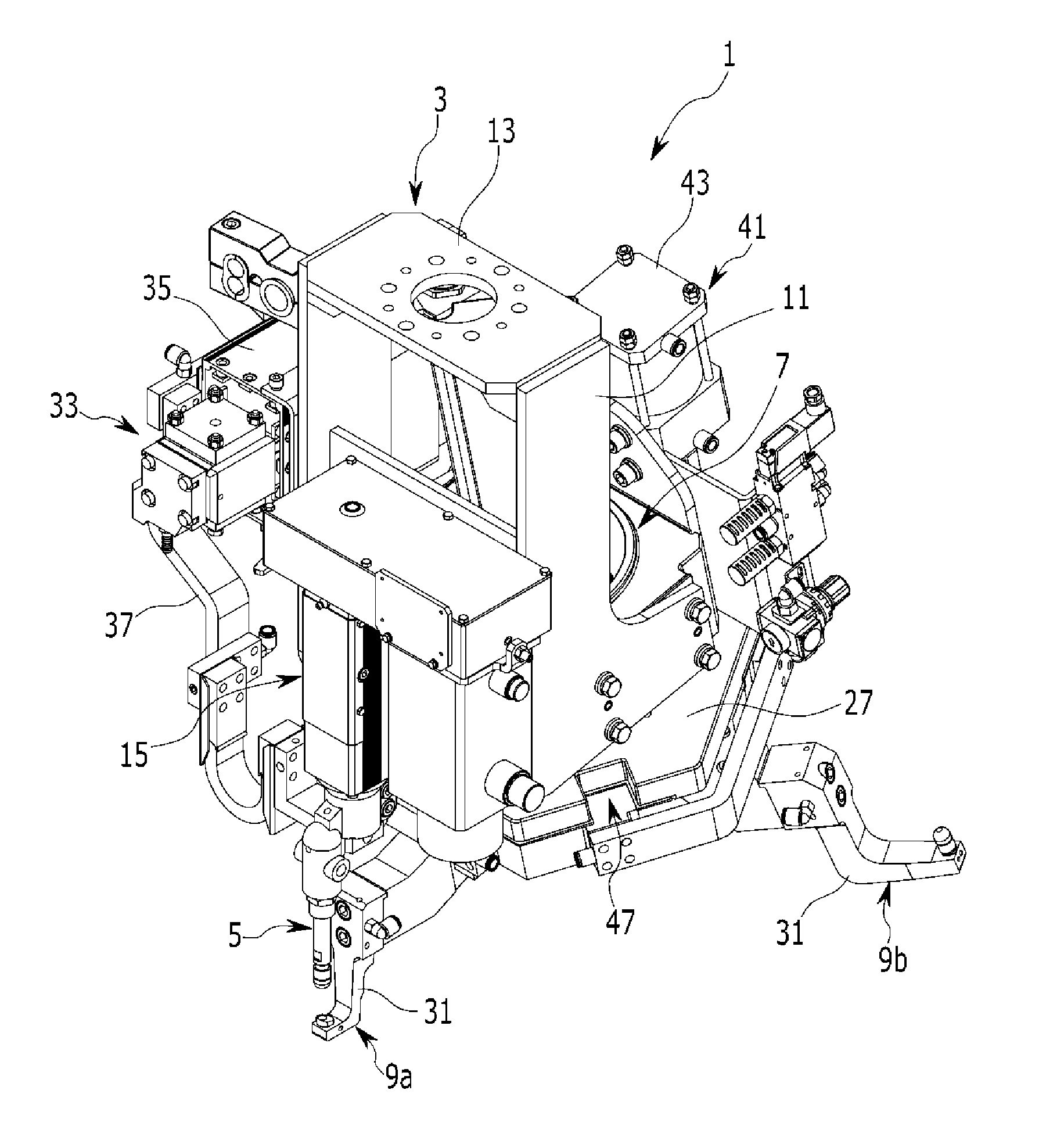
A spot welding apparatus includes: a fixed frame installed in an arm of a robot; an upper welding gun installed in one side of the fixed frame and reciprocating up and down through a pressurization unit; a rotary unit rotatably installed in a lower side of the fixed frame; and a plurality of lower welding guns installed through the rotary unit to correspond to the upper welding gun.

Description

CROSS-REFERENCE TO RELATED APPLICATION[0001]The present application claims priority of Korean Patent Application Number 10-2013-0116501 filed Sep. 30, 2013, the entire contents of which application is incorporated herein for all purposes by this reference.BACKGROUND OF INVENTION[0002]1. Field of Invention[0003]The present invention relates to a spot welding apparatus and, more particularly, to a spot welding apparatus which is commonly applicable to multiple classes by selecting a lower welding gun fitting a welding point of a welding target (i.e., a target to be welded) and performing a welding operation, and quickly performs a welding operation within a minimal time in a limited space.[0004]2. Description of Related Art[0005]In general, in manufacturing a vehicle, a vehicle body is completed by bonding various structure components such as a vehicle body panel, and the like, formed through pressing, painting and rustproofing operations are performed on surfaces of the respective co...

Claims


Application Information

Patent Timeline
IPC IPC(8): B23K11/31B23K11/11
CPCB23K11/314B23K11/311B23K11/115B23K11/315B23K2101/006B23K11/11B23K11/24B23K11/002
Inventor LEE, SO YOUNGRYU, SUNG PHIL
Owner HYUNDAI MOTOR CO LTD
Learn More