
Spot welding apparatus

Active Publication Date: 2015-07-02
HYUNDAI MOTOR CO LTD
View PDF6 Cites 14 Cited by
  • Summary
  • Abstract
  • Description
  • Claims
  • Application Information

AI Technical Summary

Benefits of technology

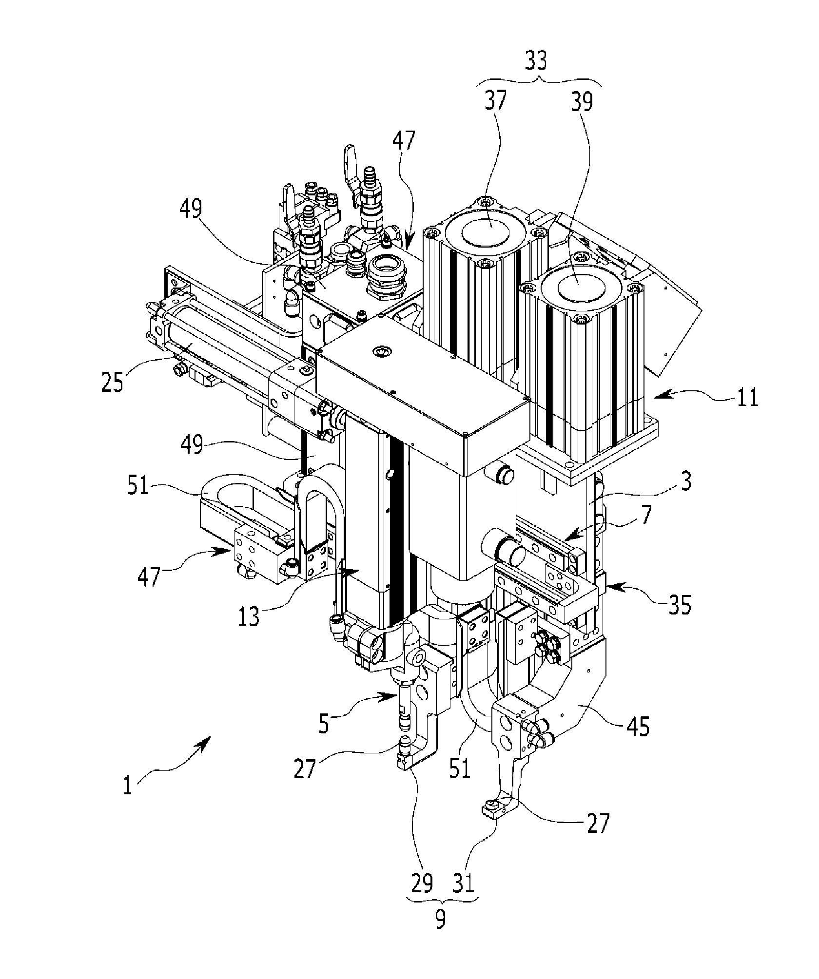
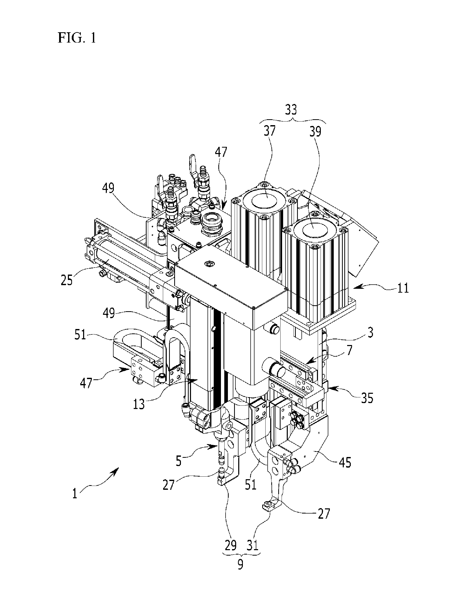
The present invention is a spot welding apparatus that can be applied to multiple vehicle models and welding spots with different shapes and positions. It improves productivity, flexibility, and efficiency of the vehicle body process and reduces the number of robots needed. It is designed to be installed in a minimum amount of space and time, which saves on installation cost. Overall, it has been developed to save money and improve efficiency in the manufacturing process of vehicles.

Problems solved by technology

However, in the conventional spot welding operation, since one spot welding apparatus is installed in the robot arm for each robot, only one spot is welded whenever the robot arm moves, and as a result, a lot of time is required to perform a predetermined number of welding spot operations, thereby degrading productivity and efficiency.
Further, lower welding guns having different shapes should be adopted according to the position and the shape of the welding spot, and as a result, facility investment costs increase, and in particular, when a plurality of robots mounted with a spot welding apparatus adopting a lower welding gun having a special shape is used, facility and maintenance costs increase and energy is excessively used.

Method used


Image

  • Spot welding apparatus
  • Spot welding apparatus
  • Spot welding apparatus

Examples


Embodiment Construction

[0030]The terminology used herein is for the purpose of describing particular embodiments only and is not intended to be limiting of the invention. As used herein, the singular forms “a”, “an” and “the” are intended to include the plural forms as well, unless the context clearly indicates otherwise. It will be further understood that the terms “comprises” and / or “comprising,” when used in this specification, specify the presence of stated features, integers, steps, operations, elements, and / or components, but do not preclude the presence or addition of one or more other features, integers, steps, operations, elements, components, and / or groups thereof. As used herein, the term “and / or” includes any and all combinations of one or more of the associated listed items.

[0031]Unless specifically stated or obvious from context, as used herein, the term “about” is understood as within a range of normal tolerance in the art, for example within 2 standard deviations of the mean. “About” can b...


PUM

PropertyMeasurementUnit
Currentaaaaaaaaaa

Abstract

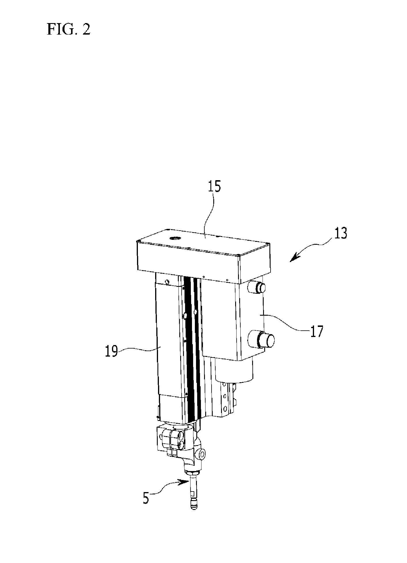
A spot welding apparatus is provided that includes a fixation panel mounted on an arm of a robot. An upper welding gun is vertically installed on a front of the fixation panel, reciprocatesvertically through a pressing unit and moves horizontally toward the fixation panel. A left and right moving unitis installed between the fixation panel and the pressing unit to move the upper welding gun horizontally. Further, two or more lower welding guns are horizontally disposed to correspond to the upper welding gun, and an upper and lower moving unit are installed on the fixation panel to reciprocate the lower welding gun vertically.

Description

CROSS-REFERENCE TO RELATED APPLICATION[0001]This application claims priority to and the benefit of Korean Patent Application No. 10-2013-0122246 filed in the Korean Intellectual Property Office on Oct. 14, 2013, the entire contents of which are incorporated herein by reference.BACKGROUND[0002](a) Field of the Invention[0003]The present invention relates to a spot welding apparatus, and more particularly, to a spot welding apparatus that performs a welding operation by selecting a lower welding gun that matches a welding spot of a welding target to be universally applied to multiple car models and enable a rapid welding operation in a limited space with a minimum time period.[0004](b) Description of the Related Art[0005]In general, during a manufacturing process of a vehicle, various structural parts such as a vehicle body panel molded by a press, and the like are bonded by a method such as welding to complete an integrated vehicle body. The completed vehicle body is painted and rust...

Claims


Application Information

Patent Timeline
IPC IPC(8): B23K11/31B23K11/11
CPCB23K11/314B23K11/115Y10S901/42B23K11/311B23K11/312B23K11/11B23K11/3072B23K11/315B23K2101/006B23K11/30
Inventor LEE, SO YOUNGRYU, SUNG PHIL
Owner HYUNDAI MOTOR CO LTD
Learn More