Container Provided with a Vacuum Pump for Cream-Type Cosmetics

a vacuum pump and cosmetic technology, applied in the field of containers provided with vacuum pumps for cream-type cosmetics, can solve the problems of only not being able to perform properly, and users not being able to pump contents

Active Publication Date: 2015-04-02
YONWOO CO LTD
View PDF7 Cites 15 Cited by
  • Summary
  • Abstract
  • Description
  • Claims
  • Application Information

AI Technical Summary

Benefits of technology

[0017]In addition, the present invention has a feature in that the said contents movement part comprises a combining pipe which is engaged into the upper part of the said pumping member, and a communicating part which forms a passage for contents which flow in through the said combining pipe, protruded upwards and combined with the said button part, and communicates with the said contents part.
[0009]This present invention has been made to solve the above-mentioned problems. The object of the present invention thereof is to provide a container with a vacuum pump for creamy-type cosmetics wherein a discharging hole of the button part is positioned to be biased, and a pressure display part is formed in the upper middle portion of the button part in order to pressurize the button part; thus a user can accurately ascertain the pressure portion of the button part, and thereby the contents can be uniformly discharged by simply pumping with one hand without causing the button part to be inclined.
[0018]As stated above, the present invention has advantages in that a discharging hole of the button part is positioned to be biased, and a pressure display part pressurizing the button part is formed in the upper middle portion of the button part; thus the user can accurately ascertain the pressure portion of the button part, and thereby the contents can be uniformly discharged by simply pumping with one hand without causing the button part to be inclined.
[0019]In addition, the present invention has advantages in that an air inflow hole is formed on the top end of the outer container and is made not to be exposed to the exterior by the support body; as a result, it not only keep the container appearance undamaged but prevent foreign substances from coming into the container through the air inflow hole.
[0020]In addition, the present invention has advantages in that, in case a user forcefully tries to separate the support body from the outer container by reverse rotation of the support body through the protrusion of the outer container and the support body, it makes the protrusion on the support body break down and thus make it possible to check the separation of the support body by examining the condition of the protrusions, which thereby discourages the user's vicious behavior.

Problems solved by technology

Due to the structure wherein the discharging hole is placed in the middle, it is not possible that a user can pump the contents by pressing the center part; instead, the pumping can only be performed through pressing either one side or both sides of the top of the button part.
However, when one side of the button part is pressed by one hand, the button part will be likely to be tilted to one side; as a result, the pumping cannot be performed properly and a problem may occur, wherein the contents cannot be discharged uniformly.
Therefore, the user should pump both sides of the button part around the discharging hole; in other words, the user should use both hands, which causes great inconvenience to the user.
On the other hand, the existing cosmetics container as the above has a structure wherein an air movement hole which forms at the bottom of the container in order for the piston to rise is exposed externally, so that it has disadvantage that dirt can is likely not only to get into through the air movement hole but also to debase the appearance of the container body.
In case the user separates the support body from the container body, however, spoilage of the contents happens.
Here have been cases wherein the user, bending the rules, uses up most of the contents and then intentionally separates the support body from the container body, and furthermore, after spoiling contents or putting foreign substance into the container body, demands exchanging the products; as a result, it is possible for sellers to have financial loss.

Method used


Image

  • Container Provided with a Vacuum Pump for Cream-Type Cosmetics
  • Container Provided with a Vacuum Pump for Cream-Type Cosmetics
  • Container Provided with a Vacuum Pump for Cream-Type Cosmetics

Examples


Embodiment Construction

[0027]In the followings, in reference with drawings, the present invention is described in detail. The same reference numbers shown in each drawing refer to the same elements.

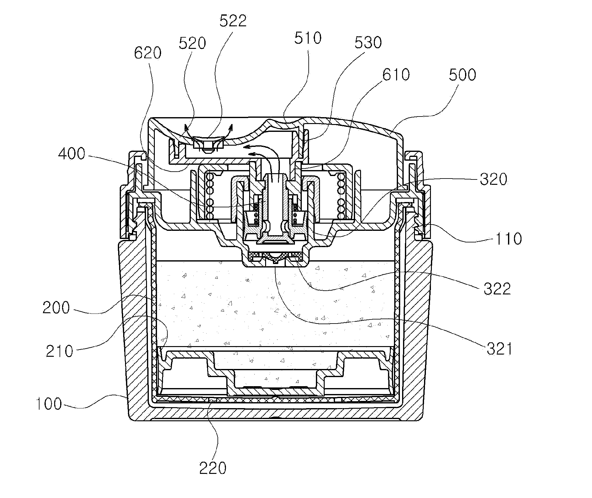
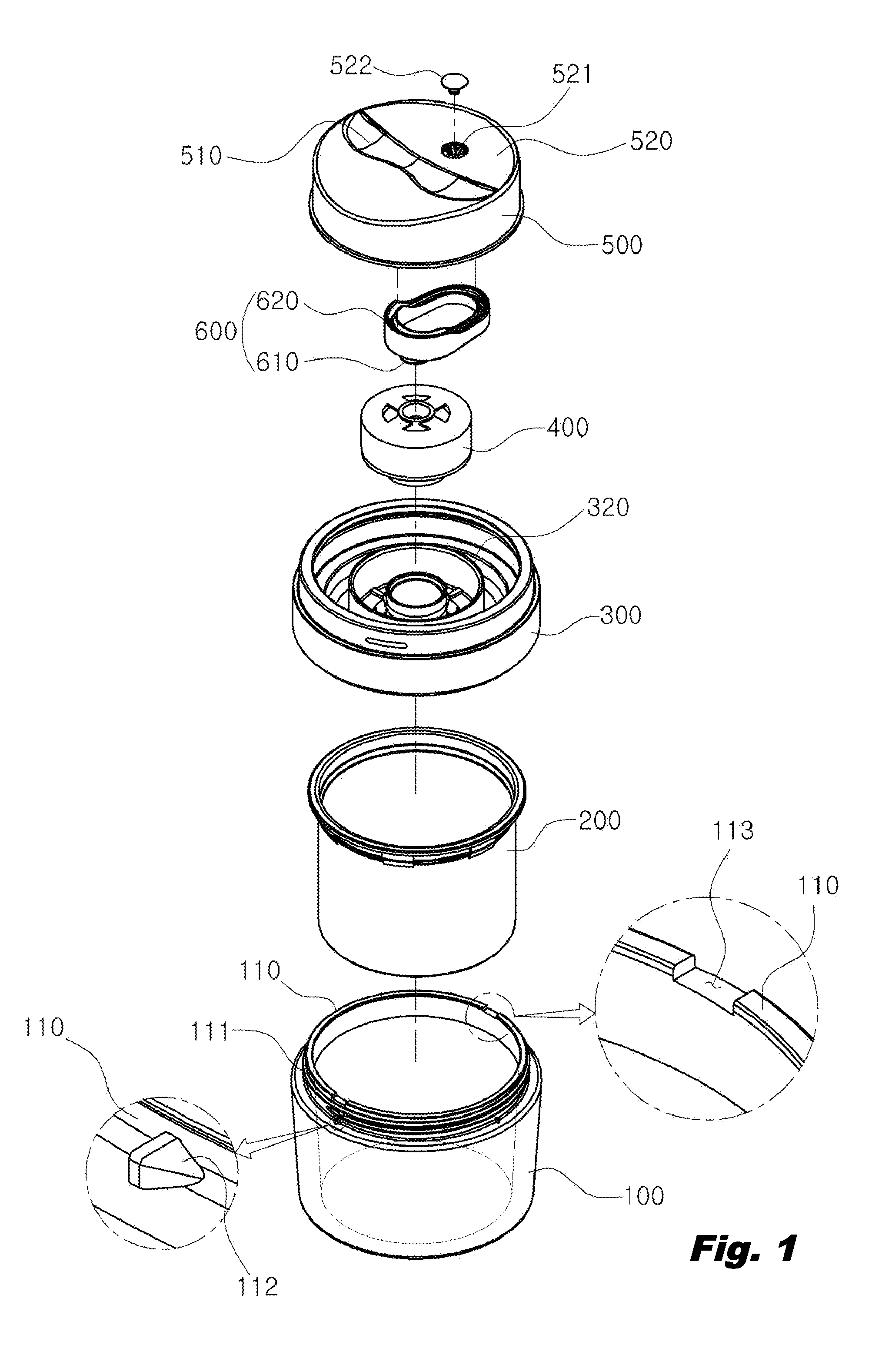
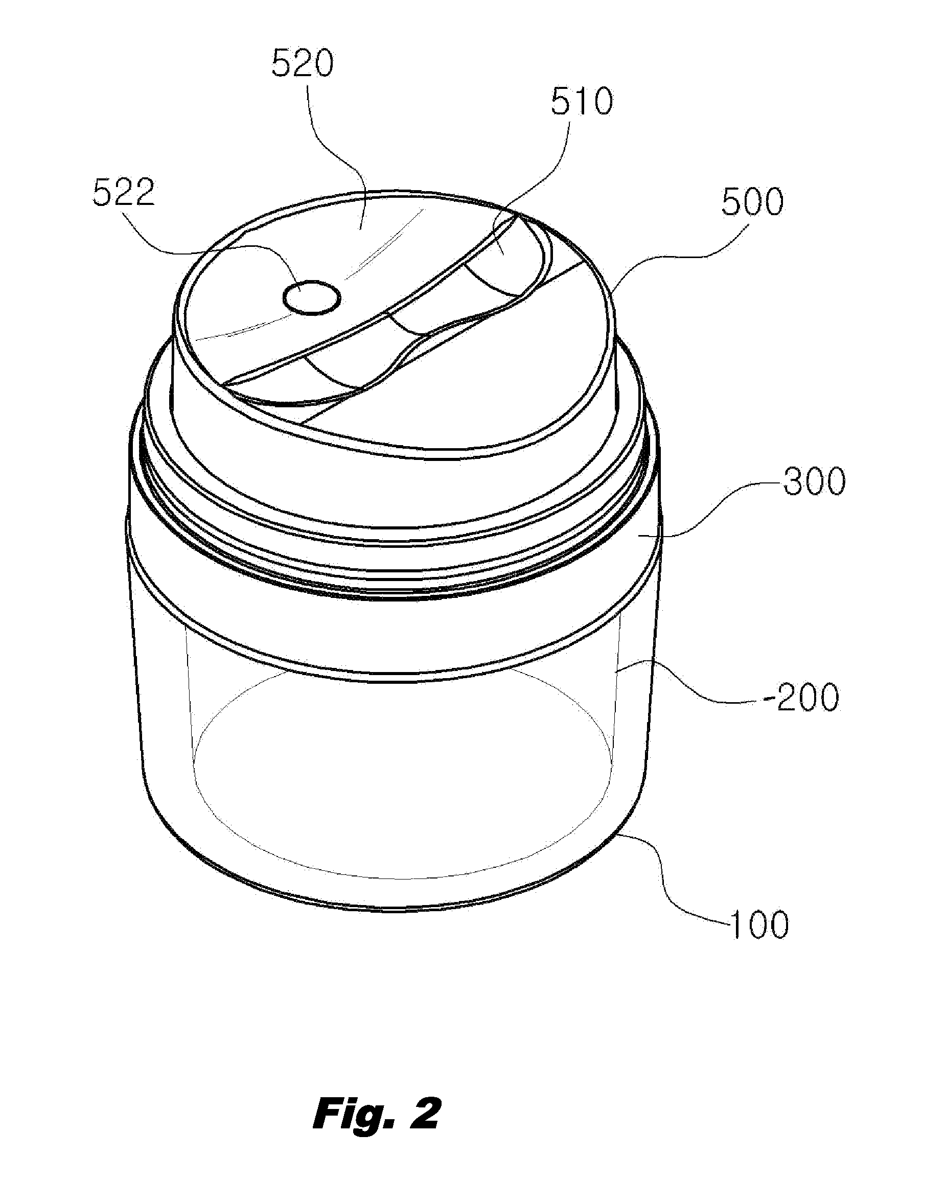
[0028]FIG. 1 is a disassembled perspective view illustrating a container provided with a vacuum pump for creamy-type cosmetics according to a preferred embodiment of the present invention, FIG. 2 is an assembled perspective view illustrating a container provided with a vacuum pump for creamy-type cosmetics according to a preferred embodiment of the present invention, and FIG. 3 is a cross-sectional view illustrating a container provided with a vacuum pump for creamy-type cosmetics according to a preferred embodiment of the present invention

[0029]FIG. 4 is an enlarged drawing of “A” part of FIG. 3 illustrating the movement of air according to the rise of piston; FIG. 5 is a use state drawing of the movement of a rotation protrusion, depending on rotation of a support body, illustrating a container provided with ...


PUM


Abstract

The present invention relates to a container provided with a vacuum pump for creamy-type cosmetics. According to the container provided with a vacuum pump for a creamy-type cosmetics of the present invention, the discharge hole of a button part is positioned so as to be biased, and a pressure display part is formed in the upper middle portion of the button part, in order to pressurize the button part and thus enable the user to accurately ascertain the pressure portion of the button part, and the contents can be uniformly discharged by simply pumping using one hand without causing the button part to incline.

Description

TECHNICAL FIELD[0001]The present invention relates to a container provided with a vacuum pump for creamy-type cosmetics. According to the container provided with a vacuum pump for a creamy-type cosmetics of the present invention, the discharge hole of a button part is positioned so as to be biased, and a pressure display part is formed in the upper middle portion of the button part, in order to pressurize the button part and thus enable the user to accurately ascertain the pressure portion of the button part, and the contents can be uniformly discharged by simply pumping using one hand without causing the button part to be inclined.BACKGROUND ART[0002]Generally, a conventional cosmetic container with a vacuum pump, having the structure that holds contents and prevents air contact, comprises: a container body which stores contents; a support body which is encirclingly combined into the upper part of the said container body and supports the pumping member; a pumping member which is co...

Claims


Application Information

Patent Timeline
Patent Type & Authority Applications(United States)
IPC IPC(8): B67D7/06B65D88/54G01F11/00
CPCA45D40/0075B05B11/0037B05B11/3023A45D2200/051A45D2200/056B05B11/007B05B11/0072B05B11/0038B05B11/0044B05B11/00446B05B11/1025B05B11/028B05B11/1059B05B11/1069B05B11/1047B05B11/1074A45D40/00B65D47/00B65D83/00A45D40/02
Inventor JUNG, SHIN-BOK
Owner YONWOO CO LTD
Why Eureka
Try Eureka