
Combined pilot valve mechanism and a shower system applied with the combined pilot valve mechanism

a combined pilot valve and shower system technology, applied in the direction of valves, mechanical devices, operating means/releasing devices, etc., can solve problems such as bad switch handles, and achieve the effects of convenient switching, small operation force, and enhanced switch handle feeling

Active Publication Date: 2015-04-02
XIAMEN SOLEX HIGH TECH IND CO LTD
View PDF7 Cites 13 Cited by
  • Summary
  • Abstract
  • Description
  • Claims
  • Application Information

AI Technical Summary

Benefits of technology

The shower system has a unique mechanism that prevents the main pipe from experiencing great water pressure. This mechanism uses a pilot valve to control the waterways, which means the control hole can have a smaller diameter, allowing for a smaller operation force and making the switch handle more comfortable. Additionally, the shower system has a fixed portion with a fixed pipe and an internal pipe that extends the on-off control distance of the control hole, allowing for the knob or rotating mechanism to be placed far away from the head shower and near to the user's hand, which makes it more convenient to switch.

Problems solved by technology

Existing shower system has many shower functions, the switch valve thereof is usually applied with a method that the switch is realized by rotating a sealing element to plug the outlet hole, the water pressure is directly working to the sealing element, so that user has to operate hard, thus making it with bad switch handle.

Method used


Image

  • Combined pilot valve mechanism and a shower system applied with the combined pilot valve mechanism
  • Combined pilot valve mechanism and a shower system applied with the combined pilot valve mechanism
  • Combined pilot valve mechanism and a shower system applied with the combined pilot valve mechanism

Examples


Embodiment Construction

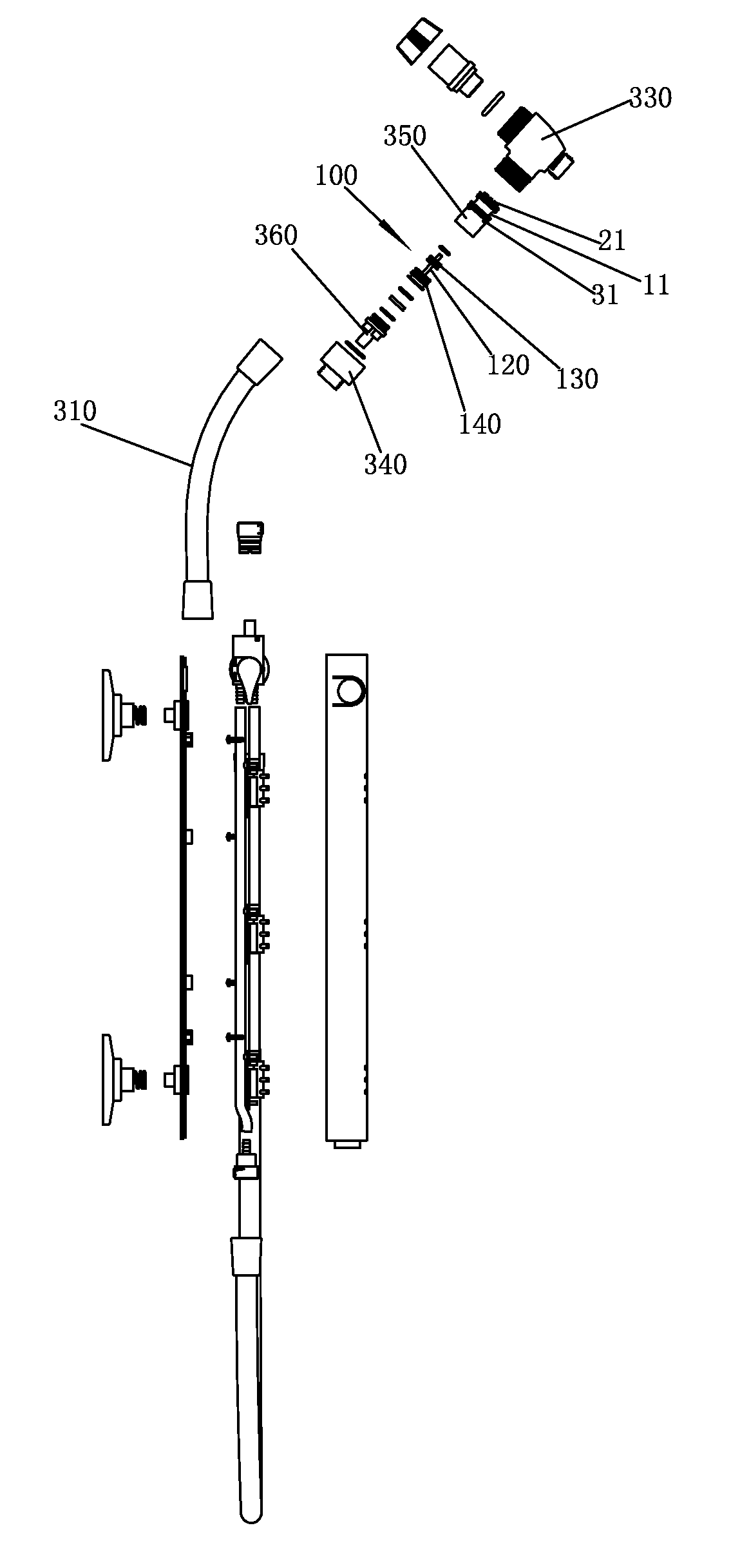
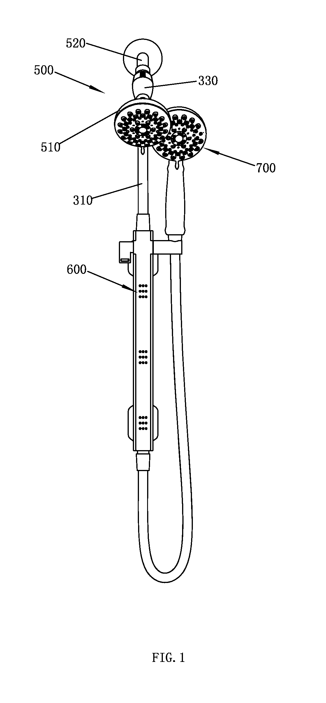
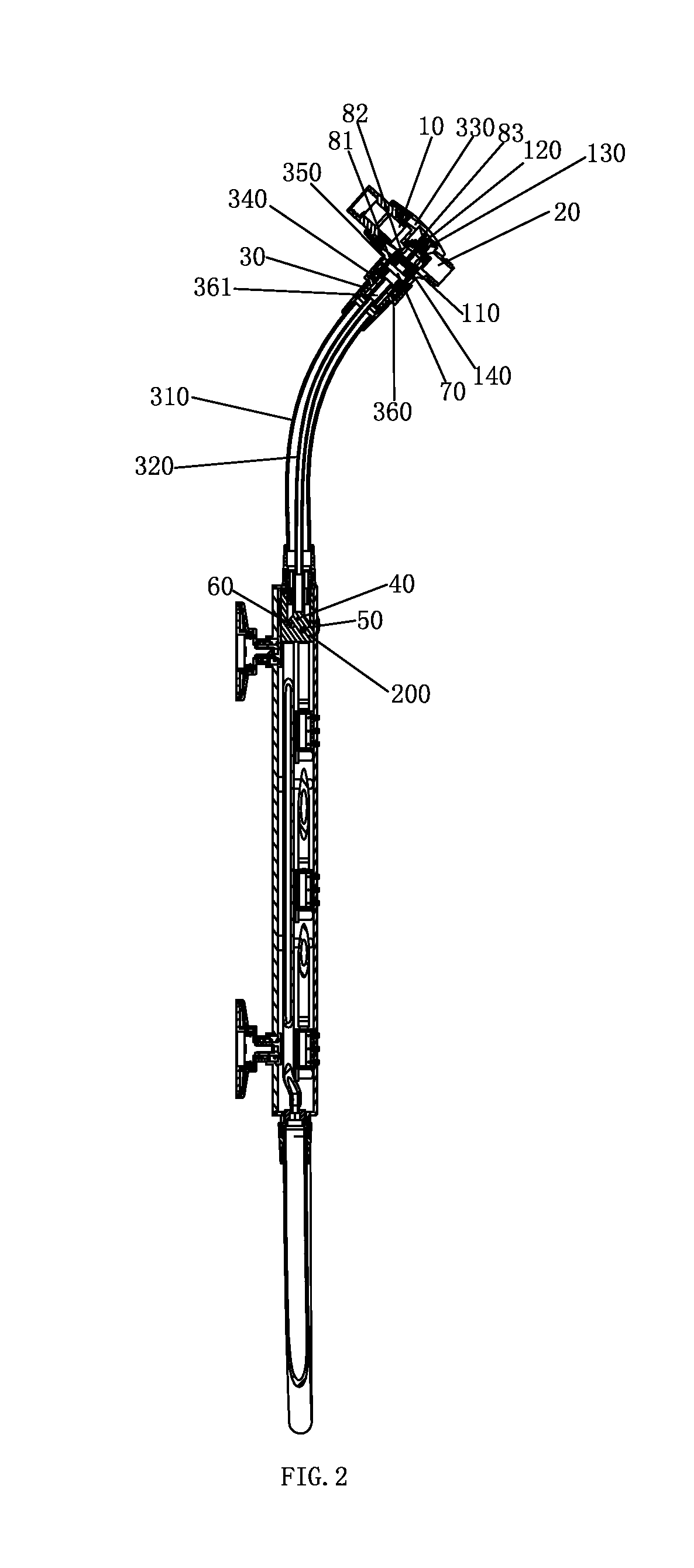
[0035]Please refer to FIG. 1 to FIG. 9, a shower system applied with a shower system applied with a combined pilot valve mechanism of a preferred embodiment is provided, the shower system comprising a first outlet terminal, a second outlet terminal, a third outlet terminal and a combined pilot valve mechanism.

[0036]The first outlet terminal is disposed with a first outlet cavity corresponding to an outlet function, the combined pilot valve mechanism is applied in the first outlet terminal. In this embodiment, the first outlet terminal is a head shower 500, the head shower 500 comprising a main section 510 and a supporting section 520, the main section 510 is disposed with the first outlet cavity, the combined pilot valve mechanism is assembled to the supporting section 520.

[0037]The second outlet terminal is disposed with a second outlet cavity corresponding to an outlet function. In this embodiment, the second outlet terminal is a side sprayer 600. The third outlet terminal is disp...


PUM


Abstract

A combined pilot valve mechanism and a shower system are applied with the combined pilot valve mechanism. By switching to close the control hole, the first water diversion hole or the second water diversion hole to control the pressures of the pressure cavity, the valve spool is driven to move to alternately close the first outlet or the second outlet, so that the inlet waterway is switched to connect to the first outlet waterway, the first water diversion hole or the second water diversion hole. As the shower system is applied with a combined pilot valve mechanism, which utilizes the control hole to switch the waterways, thus preventing the main pipe from great water pressure. The diameter of the control hole can be smaller, so that the water pressure of the button mechanism can be ignored, only friction and light elastic force of the spring exist.

Description

FIELD OF THE INVENTION[0001]The present invention relates to a combined pilot valve mechanism and a shower system applied with the combined pilot valve mechanism.BACKGROUND OF THE INVENTION[0002]Existing shower system has many shower functions, the switch valve thereof is usually applied with a method that the switch is realized by rotating a sealing element to plug the outlet hole, the water pressure is directly working to the sealing element, so that user has to operate hard, thus making it with bad switch handle.SUMMARY OF THE INVENTION[0003]The present invention is provided with a combined pilot valve mechanism and a shower system applied with the combined pilot valve mechanism, which overcome the disadvantages of the existing technology.[0004]A first technical proposal of the preset invention is as below:[0005]A combined pilot valve mechanism, wherein comprising:[0006]a fixed portion comprising an inlet waterway (10), a first outlet waterway (20) and a second outlet waterway (3...

Claims


Application Information

Patent Timeline
IPC IPC(8): B05B1/16A47K3/28E03C1/04F16K31/124F16K11/07
CPCB05B1/1681F16K31/1245A47K3/288B05B1/169E03C1/0409F16K11/07B05B1/1636B05B1/18B05B1/1663E03C1/0408Y10T137/86582
Inventor WU, YULINZHANG, MINGFUCAO, BINZHOU, HUASONG
Owner XIAMEN SOLEX HIGH TECH IND CO LTD
Features
  • Generate Ideas
  • Intellectual Property
  • Life Sciences
  • Materials
  • Tech Scout
  • Unparalleled Data Quality
  • Higher Quality Content
  • 60% Fewer Hallucinations
Learn More