Driving Device In A Self-Propelled Construction Machine And Method For Setting A Speed Ratio In Such A Driving Device

a technology of self-propelled construction and driving device, which is applied in the direction of dislodging machines, gearing, and ways, can solve the problems of increasing fuel consumption, shortening the lifespan of components, and generally not being able to couple the milling rotor, so as to reduce the wear of the device components and increase the lifespan

Active Publication Date: 2015-04-02
BOMAG
View PDF5 Cites 10 Cited by
  • Summary
  • Abstract
  • Description
  • Claims
  • Application Information

AI Technical Summary

Benefits of technology

[0012]An advantage of the present invention is further achieved for maintenance and installation work by use of a device and a method according to the present invention, in which the first drive train is disconnected and the second drive train is connected to the milling rotor. According to the present invention, connection to the secondary drive formed by the second driving unit can be established particularly easily by means of a summation transmission. A particular advantage is achieved when the secondary drive is used both for maintenance and installation work as well as for the adjustment of the speed of rotation during traveling operation and when connecting the working device. In that case, all of the said functions can be carried out by means of just one second driving unit.
[0013]An advantageous further development of the device according to one embodiment of the present invention is characterized by the fact that the gear system comprises a planetary gear with the second driving unit engaging with the planetary gear. Planetary gears make for large scale-up or scale-down ratios in compact constructions. Since the second driving unit engages within the planetary gear, the compact construction form is maintained.
[0014]The present invention is further developed according to one embodiment in that the planetary gear comprises a sun wheel, a planetary carrier comprising a number of planetary wheels, and a gear ring, the gear ring being mounted for rotation on a driving shaft, while the planetary carrier is non-rotatably connected to an output shaft, while the second driving unit engages the gear ring. To this end, the gear ring can comprise an outer intermeshing gear system as well as an inner intermeshing gear system which an output shaft of the second driving unit engages by means of an appropriate intermeshing gear system. Due to the gear ring being pivoted on the driving shaft of the gear system, it can rotate without slipping relatively to the first speed of rotation of the first driving unit and relatively to the second speed of rotation of the second driving unit. A torque converter is not required in this case, meaning that the constructive effort of the gear system can be kept to a minimum and the power output of the first driving unit can be better utilized.
[0015]In the event of the first driving unit being designed as an internal combustion engine, the engine can operate constantly at an optimum speed of rotation for the purpose of achieving a predetermined power output at minimum fuel consumption. If the first driving unit operates at a mainly constant first speed of rotation in an optimum output range, the third speed of rotation and, thus, the speed of rotation of the working device can be selected fully variably and continuously, solely by controlling or regulating the second driving unit, and, thus, the speed ratio can be adjusted as desired. During the maneuvering phase, the working device can operate at a low third speed of rotation. As there is no interruption in the force flow between the first driving unit and the working device, there is no further requirement for a slip mode for the purpose of coupling the working device, which is concomitant to a reduction in wear on the device components and an increase in their lifespan as compared with prior art devices.
[0016]A further development of the present invention is characterized in that the planetary gear comprises a sun wheel, a planetary carrier comprising a number of planetary wheels, and a gear ring, in which the planetary carrier is mounted for rotation on a driving shaft and the gear ring is non-rotatably connected to an output shaft and that the second driving unit engages the planetary carrier. To this end, the planetary carrier can comprise an outer intermeshing gear system as well as an inner intermeshing gear system that is engaged by an output shaft of the second driving unit by means of an appropriate intermeshing gear system. Due to the fact that the planetary carrier is mounted for rotation on the driving shaft of the gear system, it can rotate without slipping depending on the first speed of rotation of the first driving unit and on the second speed of rotation of the second driving unit. Here again, there is no need for a torque converter. If the first driving unit operates at a mainly constant first speed of rotation in an optimum output range, the third speed of rotation and, thus, the speed of rotation of the working device can be selected fully variably and continuously, solely by controlling or regulating the second driving unit.
[0017]The second driving unit is preferably designed in the form of a hydraulic engine. When used in construction machines, a hydraulic supply is usually provided and, thus, no additional measures are required to operate the hydraulic engine.

Problems solved by technology

Depending on the difference in speed of rotation and the inertia of the drive train, the slip mode continues for a longer period of time and the wear therefore increases, resulting in a shortening of the lifespan of the components.
Due to the predominant use of an internal combustion engine as the main drive unit with an output that is highly dependent on the speed of rotation, said engine does not operate within the optimal range due to the alternation between the idling and operating speeds, resulting in increased fuel consumption.
Coupling of the milling rotor is generally not possible while the driving unit is switched off or while it is running at the operating speed.
Due to the fact that the direction of rotation of the wheels or tracks of the construction machine corresponds to that of the milling rotor while reversing, there is a risk of the construction machine accelerating uncontrollably should the milling rotor unintentionally make contact with the ground.
Such contact can be extremely hazardous and might also lead to damage to the milling rotor.
The first driving unit is not suitable for this purpose when said unit is the main drive.
In the prior art, the use of the main drive is also not permitted for this purpose for safety reasons.
The known procedure involving the connection of said secondary drive whilst simultaneously switching off the main drive has been found to be relatively complex.

Method used


Image

  • Driving Device In A Self-Propelled Construction Machine And Method For Setting A Speed Ratio In Such A Driving Device
  • Driving Device In A Self-Propelled Construction Machine And Method For Setting A Speed Ratio In Such A Driving Device
  • Driving Device In A Self-Propelled Construction Machine And Method For Setting A Speed Ratio In Such A Driving Device

Examples


Embodiment Construction

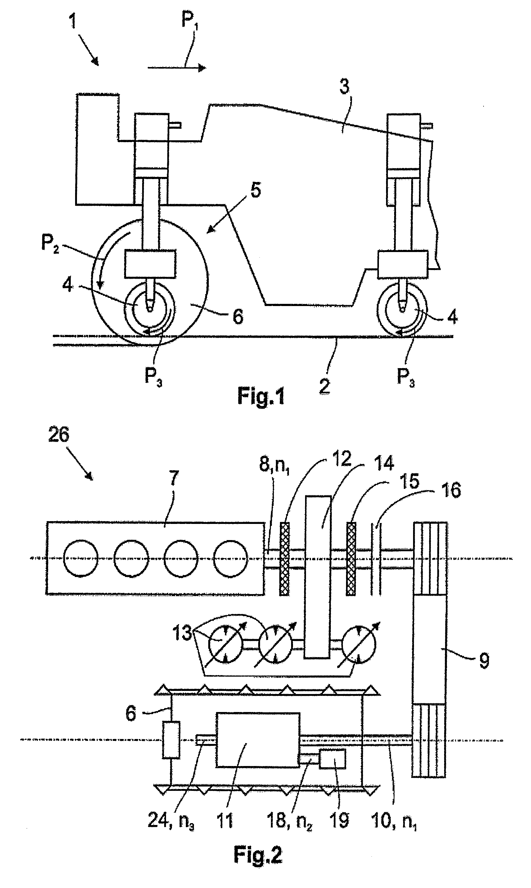
[0031]FIG. 1 illustrates a construction machine 1 in the form of a road milling machine comprising a machine frame 3 and wheels 4 adapted to process a traffic area 2. In the example shown, it comprises a working device 5 designed as a milling rotor 6. In the view shown in FIG. 1, the milling rotor 6 is in a descended working position. The direction of travel during the milling operation is identified by the arrow P1. In this case the direction of rotation of the milling rotor 6 indicated by the arrow P2 is contrary to the direction of rotation of the wheels 4 denoted by the arrow P3.

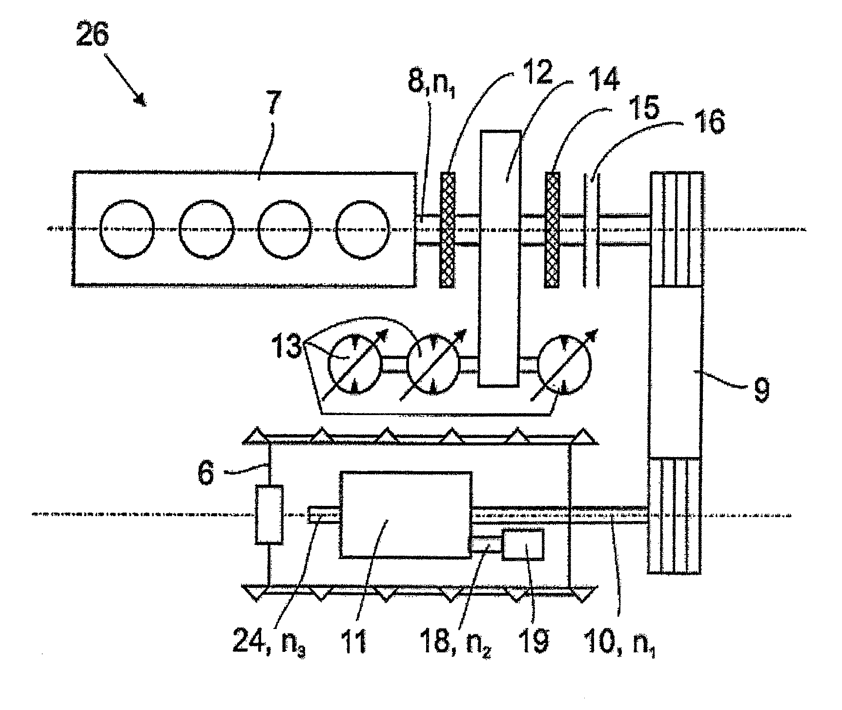
[0032]According to FIG. 2, the construction machine 1 comprises a driving device 26 for the milling rotor 6. It comprises a first driving unit 7 driving a belt transmission 9 at a first speed of rotation n1 via an output shaft 8. In this case, the first driving unit 7 is the powerful main drive of the construction machine 1 and is designed as an internal combustion engine. A decoupling unit 12, a transfe...


PUM


Abstract

The present invention relates to a device in a self-propelled construction machine with a first driving unit, which provides for a first speed of rotation (n1). By means of a planetary gear the first speed of rotation (n1) is translated into a different speed of rotation (n3) at which a working device of the construction machine, in particular a milling rotor for processing ground surfaces, can be operated.

Description

CROSS-REFERENCE TO RELATED APPLICATIONS[0001]This application is a submission under 35 U.S.C. §371 of International Application No. PCT / EP2013 / 000686, filed Mar. 8, 2013, which claims priority to German Application No. 10 2012 006 189.7, filed Mar. 27, 2012, the disclosures of which are hereby expressly incorporated by reference herein in their entireties.FIELD OF THE INVENTION[0002]The present invention relates to a driving device in a self-propelled construction machine, more particularly, a construction machine for the treatment of ground surfaces, comprising a first driving unit and a working device wherein a first drive train disposed between the first driving unit and the working device operates at a different speed of rotation. The present invention further relates to a method for effecting a change in the speed of rotation of the working device disposed within the first drive train.BACKGROUND OF THE INVENTION[0003]Examples of self-propelled construction machines are, in part...

Claims


Application Information

Patent Timeline
Patent Type & Authority Applications(United States)
IPC IPC(8): B60K25/06E01C23/12E01C23/088B60K6/12B60K6/36
CPCB60K25/06B60K6/12Y10S903/915E01C23/088E01C23/127B60K6/36B60K25/02F16H47/04B60K2025/022B60K2025/026B60Y2200/41F16H2037/088F16H2200/2005
Inventor REUTER, MARCOSCHOMAKER, RAFAELHAMMES, MANFRED
Owner BOMAG
Why Eureka
Try Eureka