Method to achieve true fail safe compliance and ultra low pin current during power-up sequencing for mobile interfaces

Active Publication Date: 2015-04-02
TEXAS INSTR INC
View PDF5 Cites 8 Cited by
  • Summary
  • Abstract
  • Description
  • Claims
  • Application Information

AI Technical Summary

Benefits of technology

[0018]FIG. 8(a) is an example graph illustrating the response of a cont

Problems solved by technology

If the IO circuit is not properly tristated, it results in high leak

Method used


Image

  • Method to achieve true fail safe compliance and ultra low pin current during power-up sequencing for mobile interfaces
  • Method to achieve true fail safe compliance and ultra low pin current during power-up sequencing for mobile interfaces
  • Method to achieve true fail safe compliance and ultra low pin current during power-up sequencing for mobile interfaces

Examples


Embodiment Construction

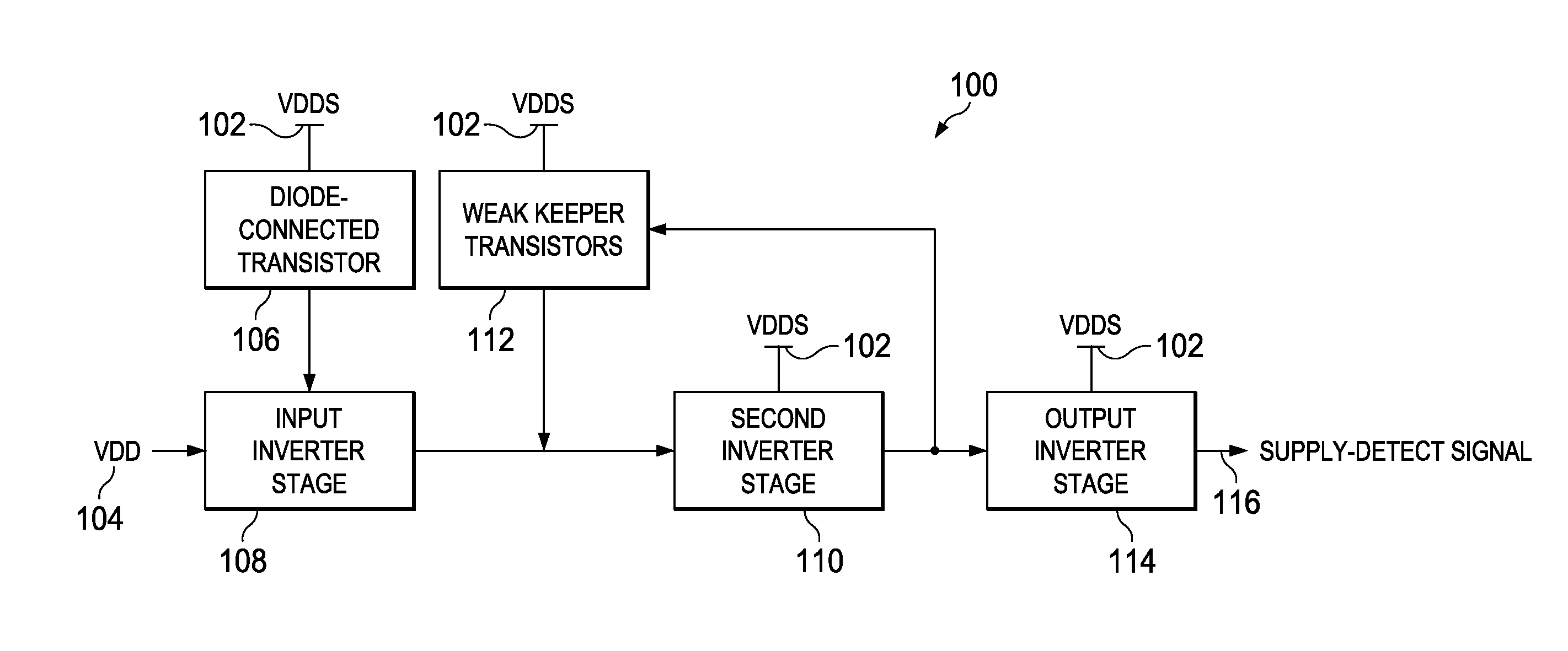
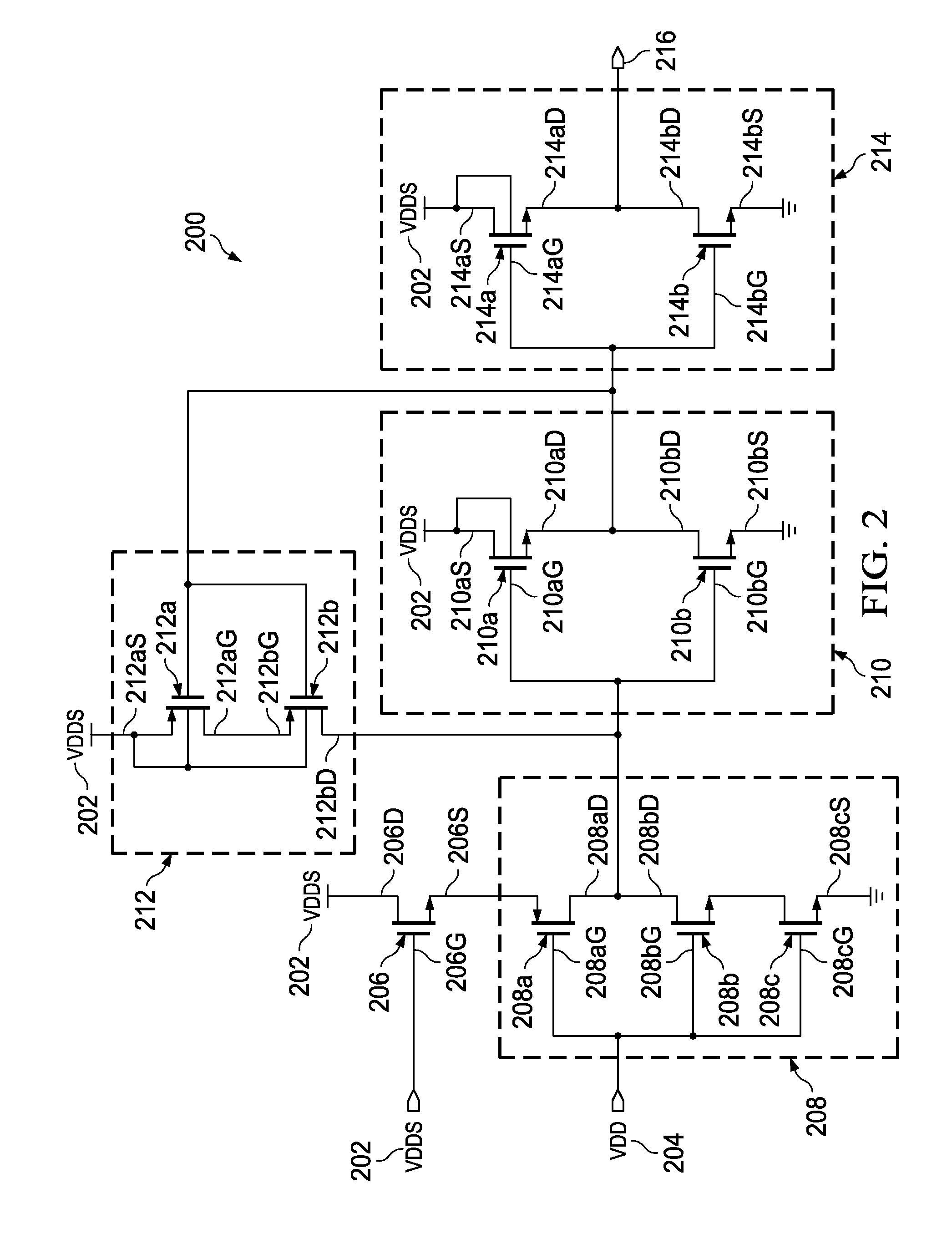
[0021]FIG. 1 illustrates a block diagram of a supply detector cell 100, according to an embodiment. The supply detector cell 100 is powered by an input / output (IO) supply voltage (VDDS) 102 and receives a core supply voltage (VDD) 104 as an input signal. A diode connected transistor 106 is powered by the IO supply voltage (VDDS) 102. The diode connected transistor 106 is one of the following, but not limited to, an NMOS transistor and a PMOS transistor. An input inverter stage 108 is coupled to the diode connected transistor 106. The input inverter stage 108 receives the core supply voltage (VDD) 104. A second inverter stage 110 receives an output of the input inverter stage 108 and is powered by the IO supply voltage (VDDS) 102. A pair of weak keeper transistors 112 is coupled to an output of the second inverter stage 110. The pair of weak keeper transistors 112 are connected in series and powered by the IO supply voltage (VDDS) 102. An output of the pair of weak keeper transistors...


PUM


Abstract

An input/output (IO) circuit powered by an input/output (IO) supply voltage. The IO circuit includes a supply detector cell that detects a core supply voltage and generates a supply detect signal. A driver circuit is connected to a PAD and the driver circuit receives the supply detect signal. A failsafe circuit receives a PAD voltage. The failsafe circuit and the supply detector cell controls a leakage current from the PAD based on the IO supply voltage and the PAD voltage.

Description

TECHNICAL FIELD[0001]Embodiments of the disclosure relate generally to integrated circuits (ICs) and more particularly to controlling PAD current or pin current during power-up sequence or power-down sequence in the integrated circuits.BACKGROUND[0002]The ever-increasing complexity and performance requirements of portable media devices call for effective system-level power management in Integrated circuits (ICs). Having one or more Switchable Power-Domains in Core-logic is a well-known low-power methodology that is employed for ICs in portable media devices. When a supply of a specific Power Domain is powered down, the outputs of that power-domain serving as inputs to IO (input / output) circuits are no longer valid and these IO circuits need to be tristated to avoid possible leakage current. An IO circuit drive / receive signals on a PAD to interface with the outside world. If the IO circuit is not properly tristated, it results in high leakage currents (conduction currents) from the P...

Claims


Application Information

Patent Timeline
IPC IPC(8): H03K19/007H03K19/0185
CPCH03K19/018521H03K19/007
Inventor RAJAGOPAL, DEVRAJ MATHARAMPALLILP., RAJAGOPALAN
Owner TEXAS INSTR INC
Why Eureka
Try Eureka