
Method for examining an object using an x-ray recording system for phase contrast imaging with displacement measurement

a technology of x-ray recording system and object, applied in the direction of material analysis using wave/particle radiation, instruments, applications, etc., can solve the problems of reducing visibility, difficult measurement method, prone to interference,

Active Publication Date: 2015-04-02
SIEMENS HEALTHCARE GMBH
View PDF0 Cites 8 Cited by
  • Summary
  • Abstract
  • Description
  • Claims
  • Application Information

AI Technical Summary

Benefits of technology

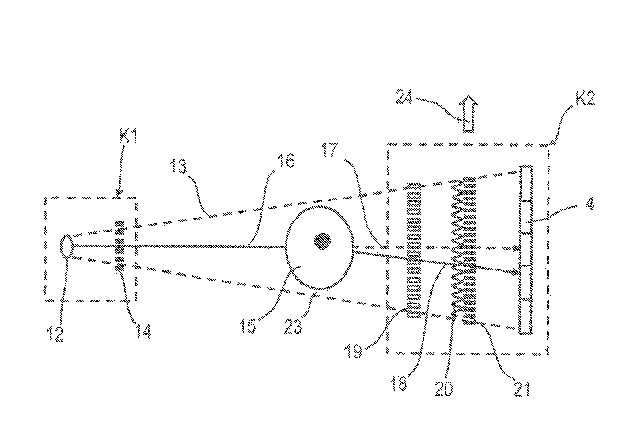
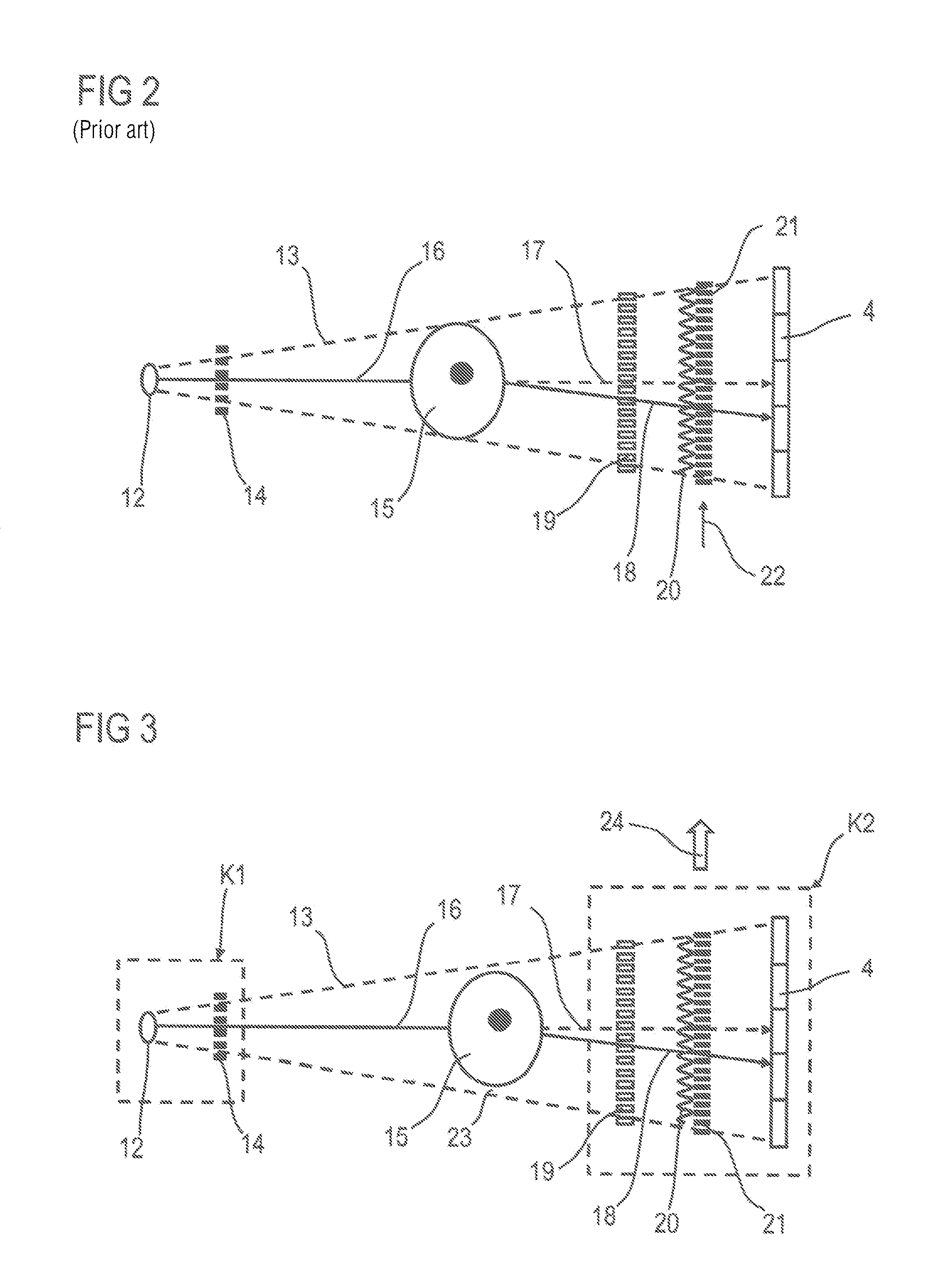
The invention is a method for examining the positions of components in an X-ray image detector system using a Talbot-Lau apparatus. The method allows for the determination of the positions of components without the need for optical measurements. The method involves aligning the X-ray beam and the X-ray recording system, moving the components relative to each other to create uncovered regions in the X-ray beam for measurement, and recording a reference image containing free fields. The position of one component is determined relative to the other component during the movement using displacement distances and reference phases calculated from pixels in the image. The image information is then determined from the partial images, displacements, and reference phases. The technical effect of this invention is to provide a more precise and accurate method for examining the positions of components in an X-ray image detector system.

Problems solved by technology

This measurement may be performed e.g. with an optical interferometer, but this method of measurement is difficult and prone to interference.
Minimum intensities greater than zero and all non-ideal properties and shortcomings of the interferometer result in a reduction in the visibility.

Method used


Image

  • Method for examining an object using an x-ray recording system for phase contrast imaging with displacement measurement
  • Method for examining an object using an x-ray recording system for phase contrast imaging with displacement measurement
  • Method for examining an object using an x-ray recording system for phase contrast imaging with displacement measurement

Examples


Embodiment Construction

[0038]Various example embodiments will now be described more fully with reference to the accompanying drawings in which only some example embodiments are shown. Specific structural and functional details disclosed herein are merely representative for purposes of describing example embodiments. The present invention, however, may be embodied in many alternate forms and should not be construed as limited to only the example embodiments set forth herein.

[0039]Accordingly, while example embodiments of the invention are capable of various modifications and alternative forms, embodiments thereof are shown by way of example in the drawings and will herein be described in detail. It should be understood, however, that there is no intent to limit example embodiments of the present invention to the particular forms disclosed. On the contrary, example embodiments are to cover all modifications, equivalents, and alternatives falling within the scope of the invention. Like numbers refer to like ...


PUM


Abstract

A method, for examining an object using an X-ray recording system, includes aligning the object in the X-ray beam and the X-ray recording system with one another such that regions in the X-ray beam are uncovered for measurement of a free field. During an X-ray image recording, the components are moved relative to one another with a lateral displacement. In a position of the relative lateral displacement of the components, a reference image containing free fields is recorded. The X-ray image recording is generated from partial images during the displacement and the position of the second component relative to the first component is determined for each partial recording such that the displacement distances of the displacements and the reference phases are calculated from a selected set of pixels and the measured intensity values thereof. Finally, the image information is determined from the partial images, the displacements and the reference phases.

Description

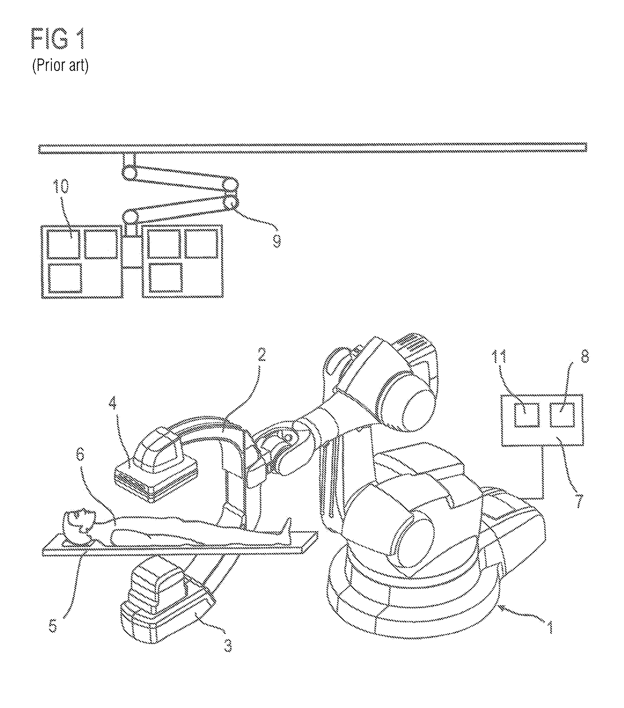
PRIORITY STATEMENT[0001]The present application hereby claims priority under 35 U.S.C. §119 to German patent application number DE 102013219554.0 filed Sep. 27, 2013, the entire contents of which are hereby incorporated herein by reference.FIELD [0002]At least one embodiment of the invention generally relates to a method for examining an object using an X-ray recording system for phase contrast imaging having at least one X-ray emitter for generating a quasi-coherent X-ray beam, an X-ray image detector with pixel elements arranged in a matrix, a diffraction or phase grating which is arranged between the object and the X-ray image detector, and an analyzer grating associated with the phase grating for generating an intensity pattern or interference pattern.BACKGROUND [0003]For a new method for stochastic phase scanning, X-ray phase contrast imaging using a Talbot-Lau apparatus, which is dealt with in a parallel application, it is necessary to measure the relative lateral distance of ...

Claims


Application Information

Patent Timeline
IPC IPC(8): A61B6/00
CPCA61B6/4291A61B6/484A61B6/4441A61B6/4233A61B6/4283A61B6/4458
Inventor ANTON, GISELABAYER, FLORIANDURST, JURGENMICHEL, THILOPELZER, GEORGRIEGER, JENSWEBER, THOMAS
Owner SIEMENS HEALTHCARE GMBH
Learn More