Microfluidic cartridge devices and methods of use and assembly

a technology of microfluidic cartridges and cartridges, which is applied in the direction of positive displacement liquid engines, machines/engines, laboratory glassware, etc., can solve the problems of high fluidic capacitance, high variability, and potential waste, and achieves simple construction geometry, cost-effective manufacturing, and reduced reagent volumes

Active Publication Date: 2015-04-02
BIO RAD LAB INC
View PDF9 Cites 43 Cited by
  • Summary
  • Abstract
  • Description
  • Claims
  • Application Information

AI Technical Summary

Benefits of technology

[0006]In one aspect, a cartridge is provided for a microfluidic system, where the reagents are stored, integrated within the cartridge in sealed reservoirs so as not to flow into the microfluidic device until dictated by operation. This allows for long term storage of cartridges containing reagents, while protecting the reagents and microfluidic device from contamination and degradation. In operation, the cartridge reduces reagent volumes required, by keeping the microfluidic device in close proximity to its reagent source and waste reservoirs. In one aspect, a mechanism is provided for controlling the flow within microfluidic channels of a microfluidic cartridge device. The mechanism may be a valve integrated directly onto the microfluidic device of the cartridge. An advantage of the devices described herein includes a valve in a microfluidic system having simple construction geometry, allowing cost-effective manufacture of valve features and components. Another advantage is a very small volume, appropriate to the smaller volumes of fluid being employed in microfluidic devices, as compared to any non-integrated off-device valve.

Problems solved by technology

This requires complex manipulation of tubing and connectors, creating the potential for waste, due to leaks or operator errors.
Reagent leaks and handling contamination are a considerable source of variability in system operation.
These pumps have high fluidic capacitances and often require cumbersome fluidic pre-preparation.
The process can result in long settling times and unsteady fluidic transients.
When a microfluidic device has many fluid inputs and outputs connecting to any syringes with many ports for tubing, the complexity of the device increases along with the cost of fabrication, assembly and operation.

Method used


Image

  • Microfluidic cartridge devices and methods of use and assembly
  • Microfluidic cartridge devices and methods of use and assembly
  • Microfluidic cartridge devices and methods of use and assembly

Examples


Embodiment Construction

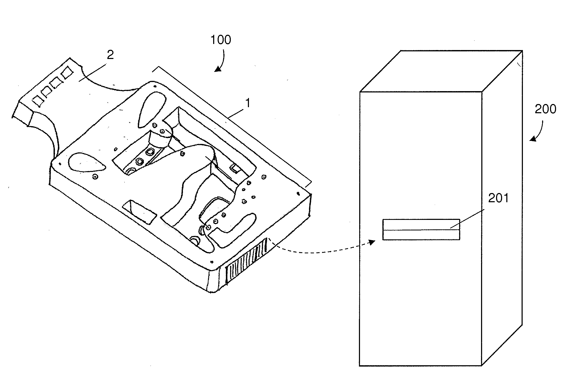
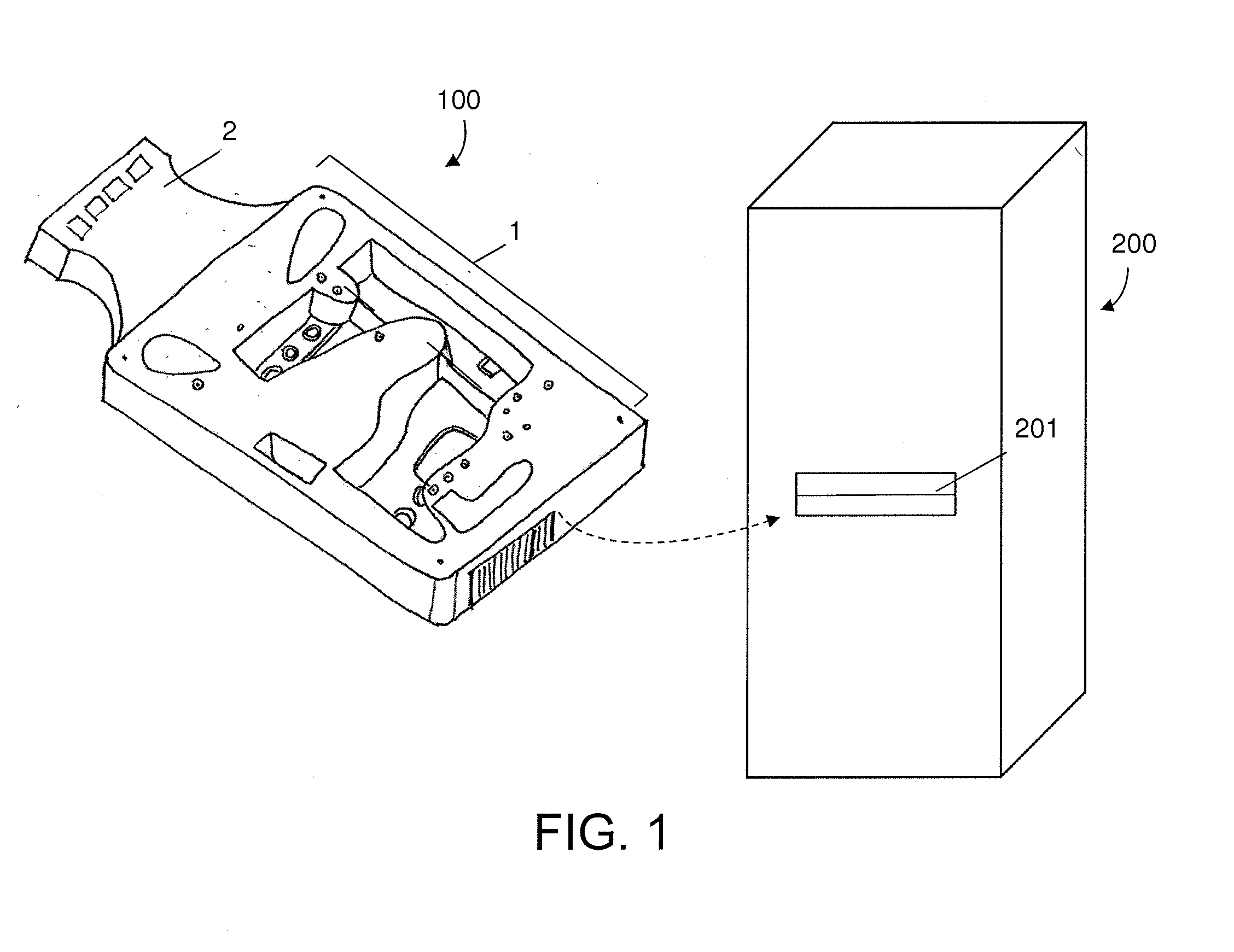
[0037]A variety of aspects for use in microfluidic cartridge systems are provided herein, including but not limited to methods and structures for controlling fluid flow of reagents stored within a microfluidic cartridge for performing an assay for detection of a target analyte in a fluid sample. The methods, devices and systems described herein can be used in isolation or adapted to any number of different microfluidic system configurations. One such system is depicted in FIG. 1. It should be recognized that the system of FIG. 1 is not intended to limit the invention. For example, aspects of the system of FIG. 1 can be used in separation from other aspects of the system while using the inventive configurations described herein.

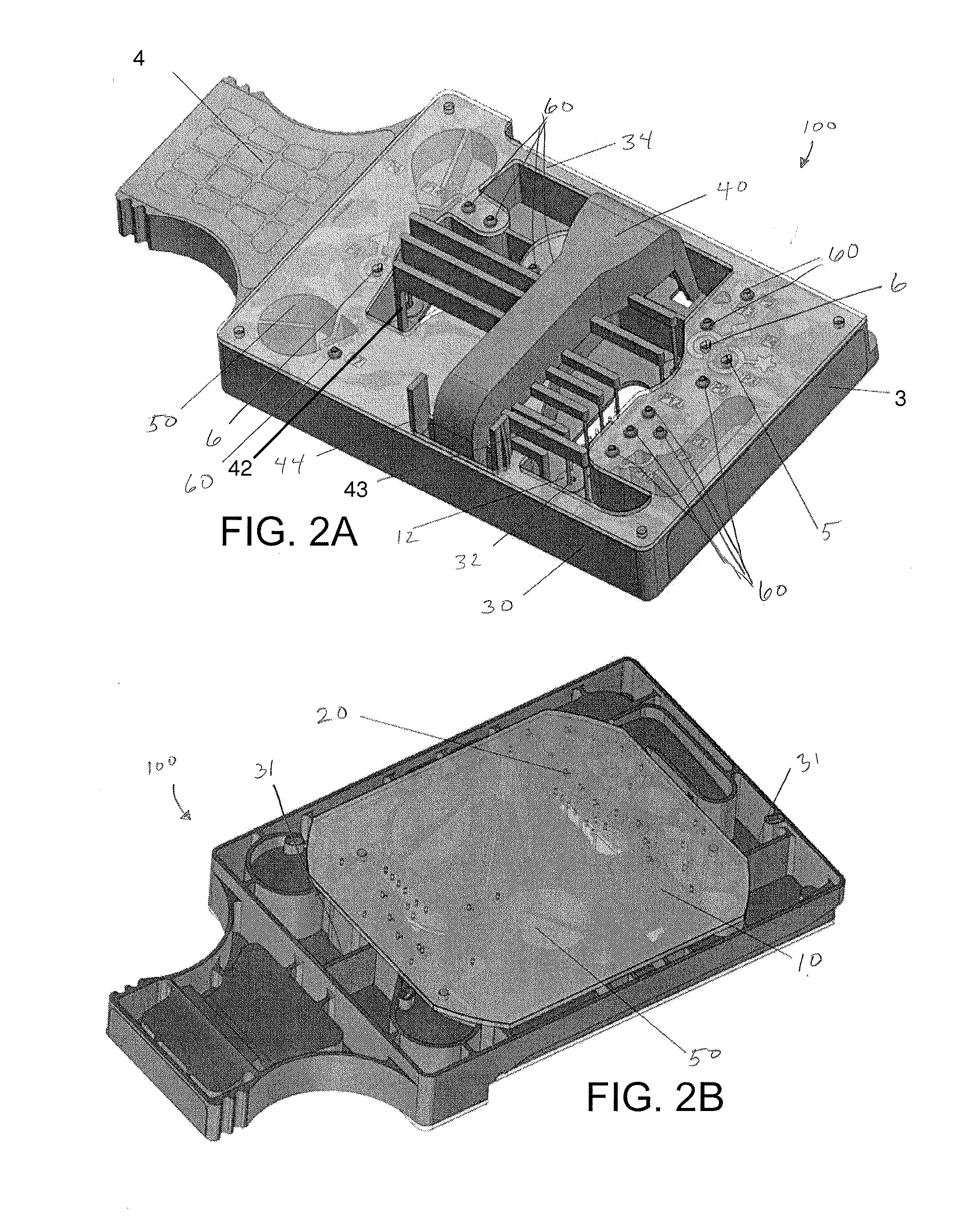
[0038]In one or more embodiments, the system comprises a microfluidic cartridge having a microfluidic device with a network of microfluidic channels adapted for performing an assay and one or more reservoirs for containing a reagent for use in the assay. In on...


PUM


Abstract

Methods and systems for controlling fluid flow through a cartridge for use in an assay of a fluid sample for detection of a target analyte. In one aspect, the cartridge includes a microfluidic device having a network of microfluidic channels, one or more reservoirs and one or more actuatable valves for controlling fluid flow from the reservoirs through the microfluidic channels. In some embodiments, the valve includes a deformable membrane movable between a closed configuration in which the membrane seals against the microfluidic device inhibiting fluid flow and an open configuration moved away from the microfluidic device to allow fluid flow through the microfluidic channels. Other valve embodiments utilize frangible membranes or user-removable membrane.

Description

CROSS-REFERENCES TO RELATED APPLICATIONS[0001]The present application claims benefit of priority to U.S. Provisional Patent Application 61 / 884,432, filed Sep. 30, 2013, the entire contents of which are incorporated herein by reference.[0002]The present application is related to PCT Application No. US2013 / 059517, filed Sep. 12, 2013; and U.S. Non-Provisional application Ser. No. 14 / 470,860 filed Aug. 27, 2014; each of which is incorporated by reference in its entirety.BACKGROUND OF THE INVENTION[0003]Microfluidic devices require a source of liquid reagents to operate. Typically for emulsion-based systems, these reagents are stored in bottles or tubes which are then connected to the device by the user, with tubing and connectors. This requires complex manipulation of tubing and connectors, creating the potential for waste, due to leaks or operator errors. Reagent leaks and handling contamination are a considerable source of variability in system operation.[0004]By their very nature, m...

Claims


Application Information

Patent Timeline
Patent Type & Authority Applications(United States)
IPC IPC(8): B01L3/00
CPCB01L3/502738B01L3/50273B01L3/502784B01L2400/0487B01L2200/10B01L2300/0887B01L2200/0621B01L2300/0672B01L2400/0683B01L2300/087B01L2200/16B01L2300/0867B01L2400/0638B01L2400/0655F16K99/0015F16K99/0059B01L2200/025B01L2200/0684B01L2300/021B01L2300/0654B01L2400/0688F16K99/00
Inventor KIANI, SEPEHRHUNG, TONYSTOKES, PETERSHARPE, JULIAABATE, ADAMESMAIL, ADNAN
Owner BIO RAD LAB INC
Why Eureka
Try Eureka