

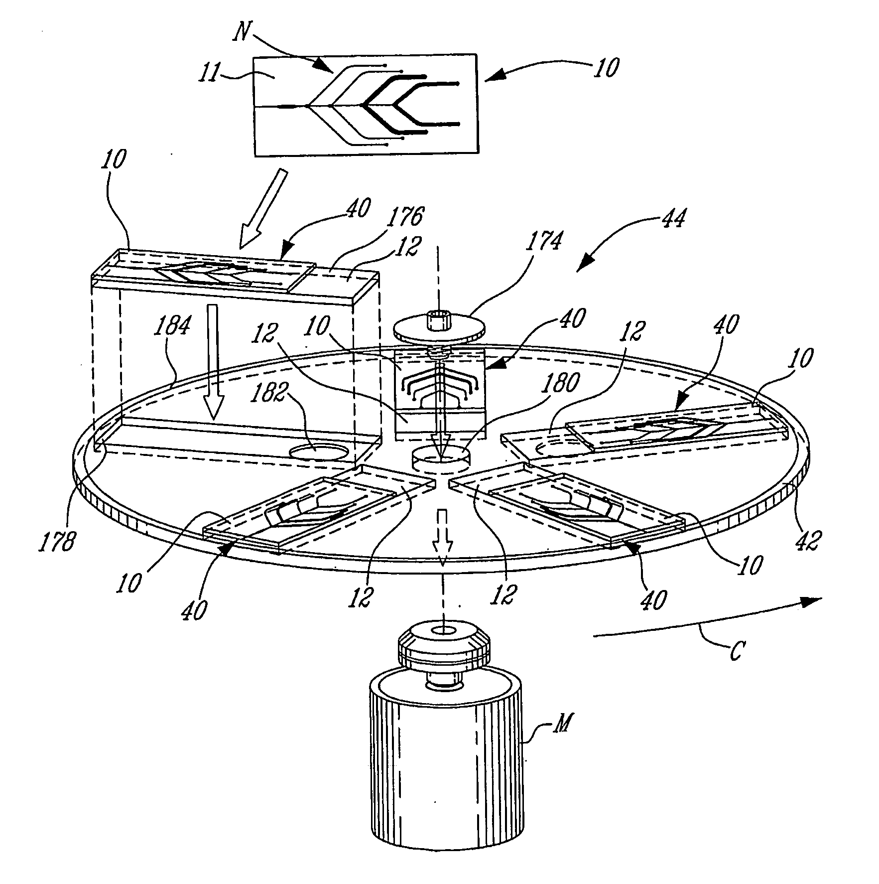
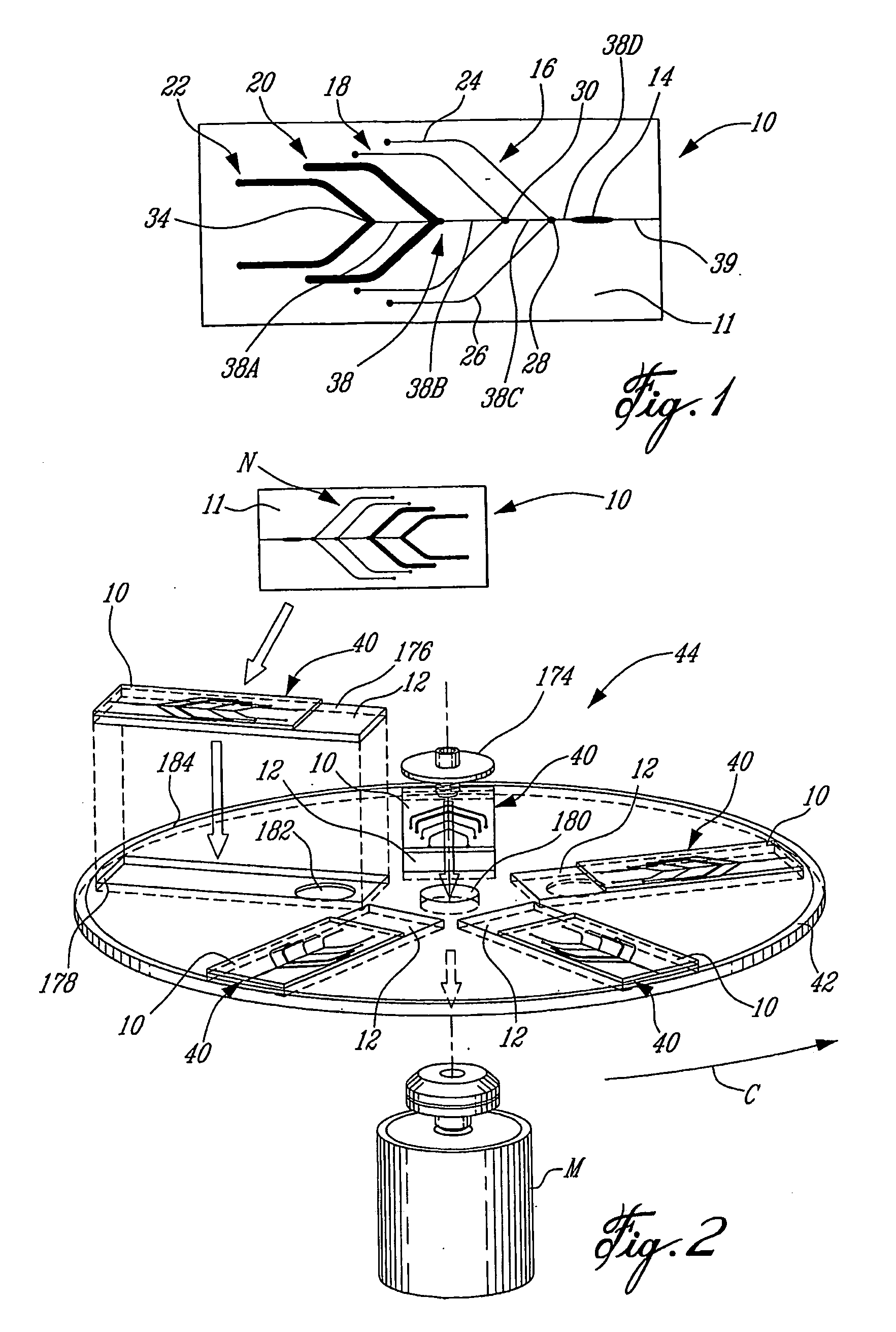
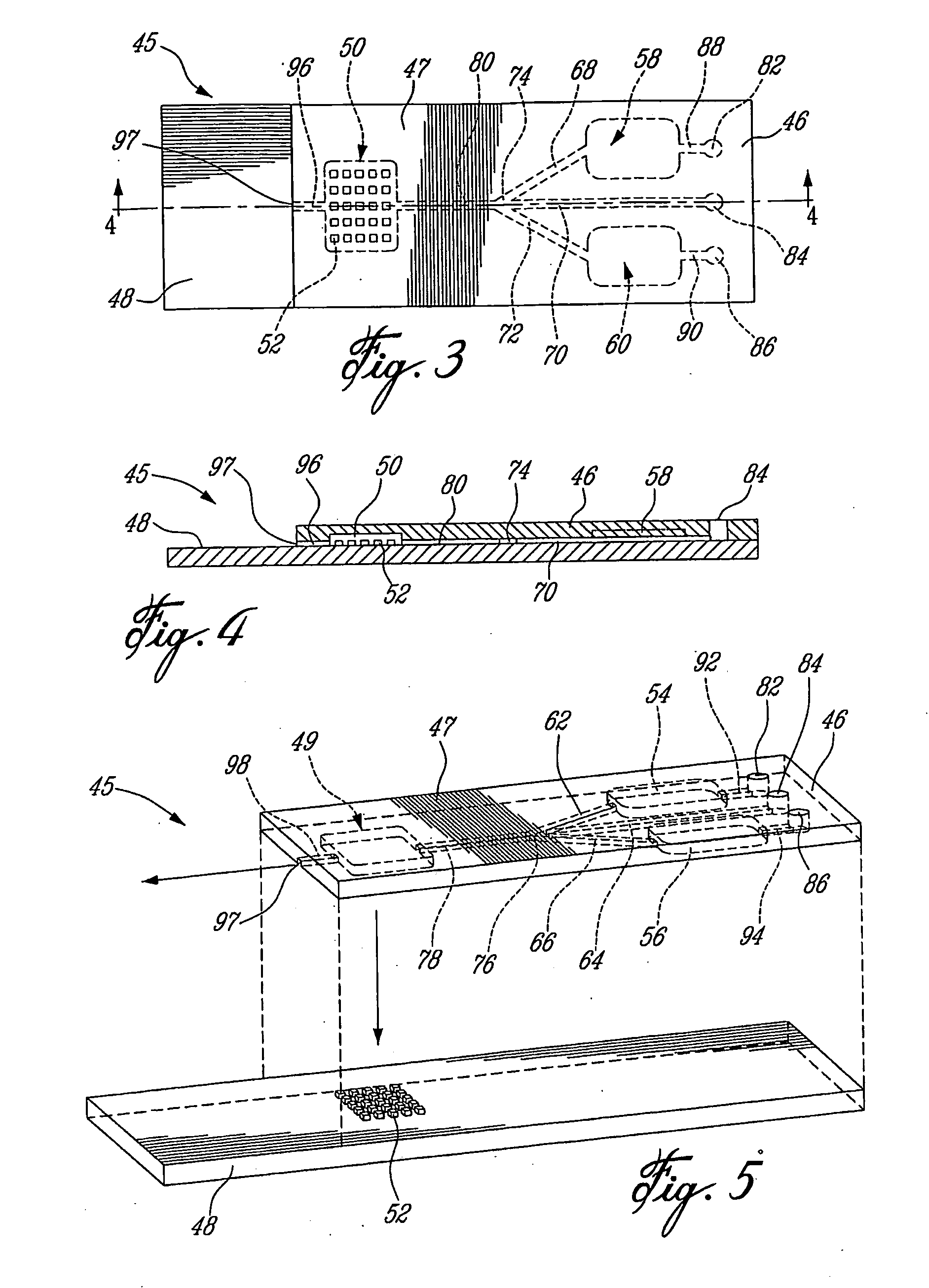
Removable microfluidic cell
a microfluidic cell and flow cell technology, applied in the field of microfluidics, can solve the problems of slow process requiring between 3 and 16 hours, burdensome detection of foregoing reaction, and low ionic strength solution, and achieve rapid and simple removal of fluidic system, reduce reaction time and reagent volume, and increase reaction reproducibility.
- Summary
- Abstract
- Description
- Claims
- Application Information
AI Technical Summary
Benefits of technology
Problems solved by technology
Method used
Image

Examples
example 1
Removable Fluidic System to Drive Microarray Reagents Using Centrifugal Force
Materials and Methods
Selection of PCR Primers and Capture Probes
[0135]All chemical reagents were obtained from Sigma-Aldrich Co. (St-Louis, Mich.) and were used without further purification unless otherwise noted. Oligodeoxyribonucleotide capture probes, which were 5′-modified by the addition of two nine carbon spacers and an amino-linker, were synthesized by Biosearch Technologies (Novato, Calif.). The amino-linker modification permits the covalent attachment of probes onto a functionalized glass surface. Four capture probes were used: S. aureus targeting probe (5′-CGTATTATCAAAAGACGAAG-3′), S. epidermidis targeting probe (5′-CAIAGCTGAAGTATACGTAT-3′), S. haemolyticus targeting probe (5′-CAAAATTTAAAGCAGACGTATA-3′) and S. saprophyticus targeting probe (5′-AAAGCGGATGTTTACGTTTT-3′). Primer pairs TstaG422 (5′-AAAGCGGATGTTTACGTTTT-3′) and TstaG765 (5′-TIACCATTTCAGTACCTTCTGGTAA-3′) were used to amplify all staphyl...
PUM
| Property | Measurement | Unit |
|---|---|---|
| depth | aaaaa | aaaaa |
| depth | aaaaa | aaaaa |
| diameter | aaaaa | aaaaa |
Abstract
Description
Claims
Application Information