Wafer processing method

a processing method and wafer technology, applied in the field of wafer processing method, can solve problems such as and achieve the effect of preventing unintentional cracking of wafers and preventing cracking of wafers

Active Publication Date: 2015-04-09
DISCO CORP
View PDF1 Cites 10 Cited by
  • Summary
  • Abstract
  • Description
  • Claims
  • Application Information

AI Technical Summary

Benefits of technology

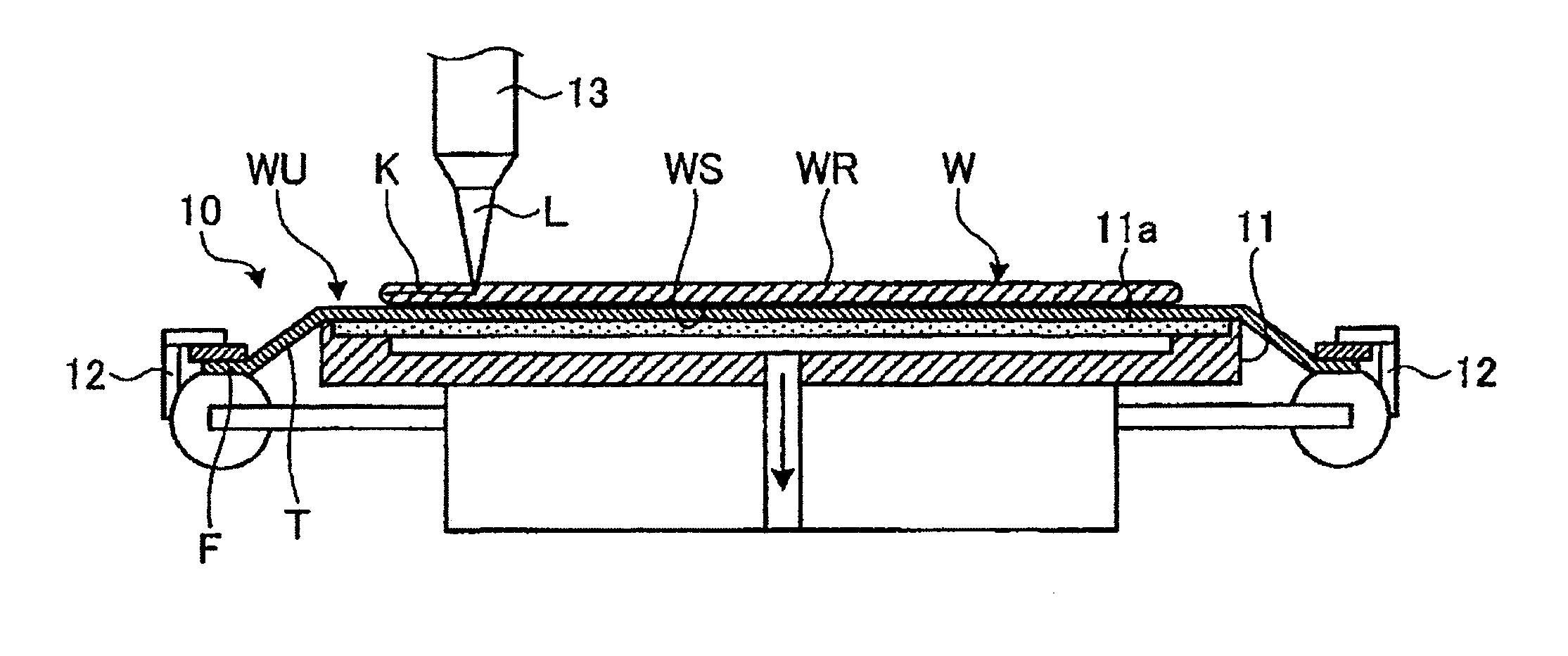
[0010]In the wafer processing method according to the present invention, a fluid is blown from the holding surface of the chuck table against the adhesive tape in order to cancel the close contact between the adhesive tape and the holding surface. Accordingly, it is possible to prevent cracking of the wafer due to forcible separation of the wafer from the holding surface. That is, it is possible to prevent unintentional cracking of the wafer in which the modified layers have already been formed.

Problems solved by technology

Particularly in the case that a modified layer is formed inside the wafer along each division line by using a laser beam, there is a possibility that the wafer may be unintentionally cracked.

Method used


Image

  • Wafer processing method
  • Wafer processing method
  • Wafer processing method

Examples


Embodiment Construction

[0023]A preferred embodiment of the present invention will now be described in detail with reference to the drawings. The present invention is not limited to this preferred embodiment. Further, the components used in this preferred embodiment may include those that can be easily assumed by persons skilled in the art or substantially the same elements as those known in the art. Further, the configurations described below may be suitably combined. Further, the configurations may be variously omitted, replaced, or changed without departing from the scope of the present invention.

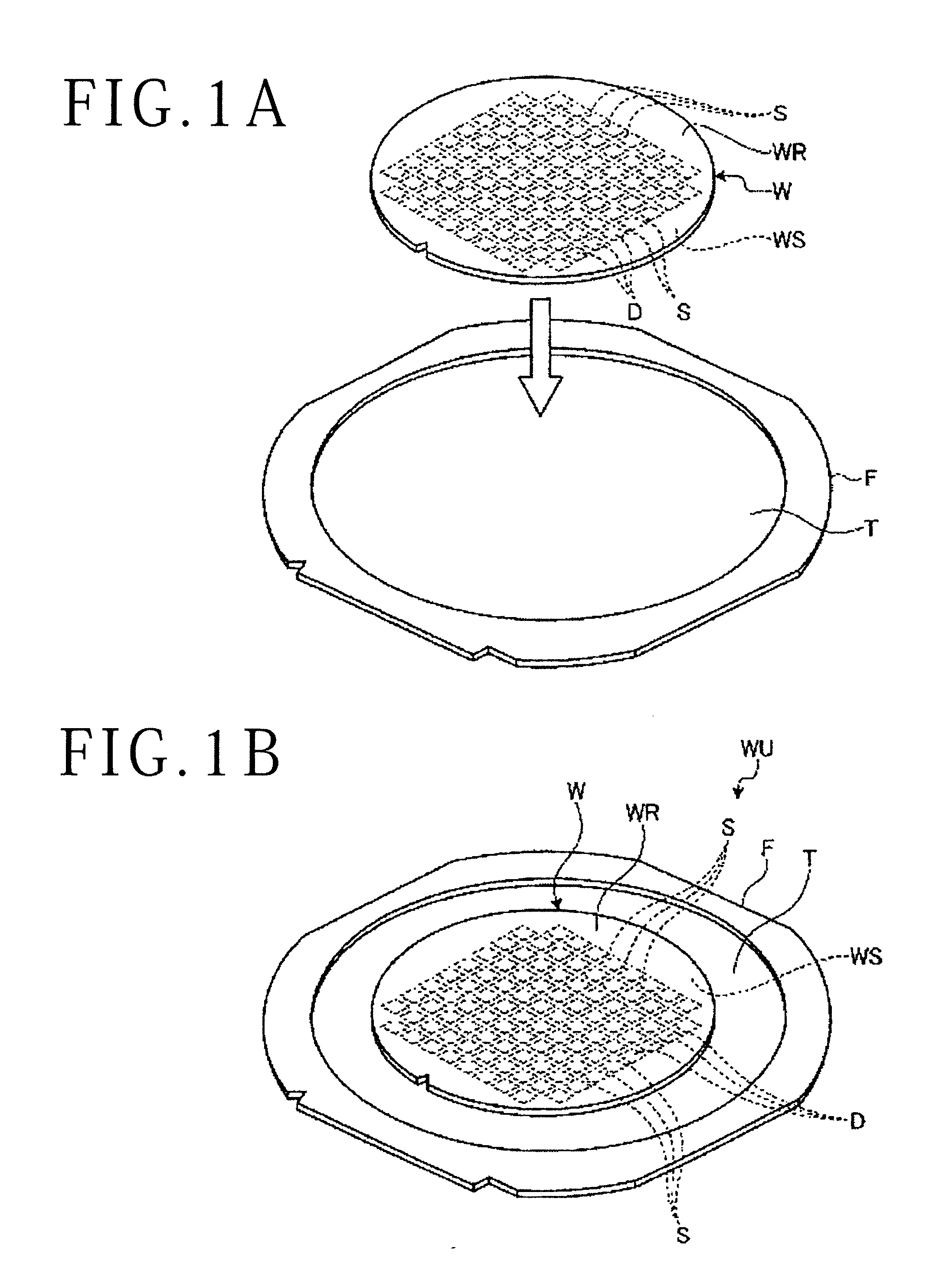
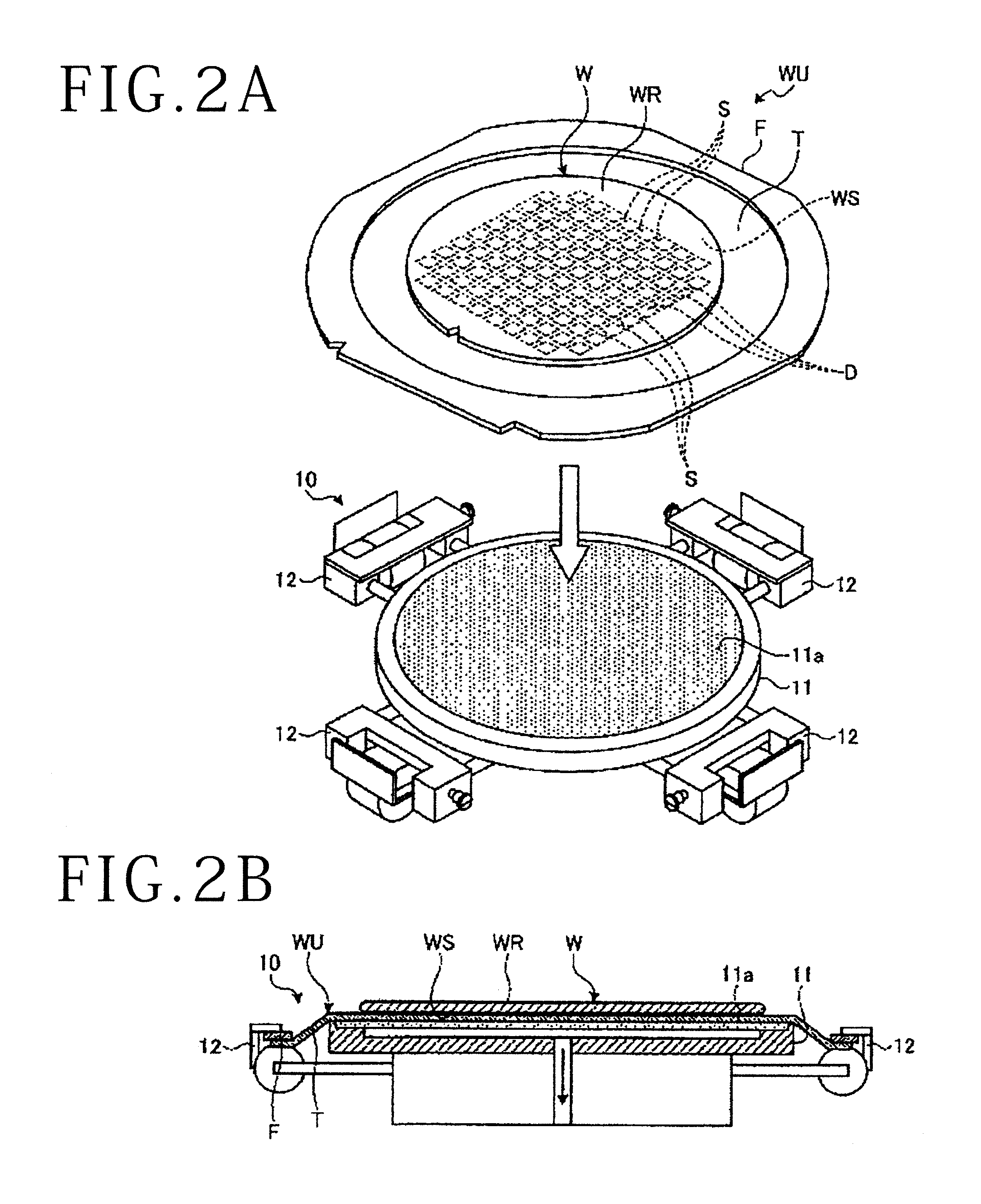
[0024]A wafer processing method according to this preferred embodiment will now be described with reference to FIGS. 1A to 6B. The wafer processing method (which will be hereinafter referred to simply as processing method) according to this preferred embodiment is a method of processing a wafer W shown in FIG. 1A. More specifically, the processing method according to this preferred embodiment is a method of app...


PUM

PropertyMeasurementUnit
widthaaaaaaaaaa
transmission wavelengthaaaaaaaaaa

Abstract

A wafer processing method includes a wafer unit forming step of supporting a wafer through an adhesive tape to an annular frame to thereby form a wafer unit, a wafer unit holding step of holding the wafer through the adhesive tape on a holding surface of a chuck table under suction, a processing step of applying a laser beam to the wafer held on the chuck table to thereby form a modified layer inside the wafer, an unloading step of unloading the wafer unit from the chuck table, and a dividing step of dividing the wafer along the modified layer as a division start point. The wafer processing method further includes a close contact canceling step of blowing a fluid from the holding surface against the adhesive tape after performing the processing step to thereby cancel the close contact between the adhesive tape and the holding surface.

Description

BACKGROUND OF THE INVENTION[0001]1. Field of the Invention[0002]The present invention relates to a wafer processing method.[0003]2. Description of the Related Art[0004]In a semiconductor device fabrication process, a plurality of devices such as ICs, LSIs, and MEMS (Micro Electro Mechanical Systems) devices are formed on the front side of a substantially disk-shaped semiconductor wafer. These plural devices are formed in a plurality of separate regions defined by a plurality of crossing division lines called streets. The semiconductor wafer thus having the plural devices is cut along the streets to thereby divide the plural separate regions where the plural devices are formed from each other. Thus, a plurality of device chips corresponding to the plural devices are manufactured.[0005]Until recent years, cutting of the semiconductor wafer has been performed by using a cutting apparatus having a cutting blade. However, since a division groove having a width of about 20 to 40 μm is for...

Claims


Application Information

Patent Timeline
Patent Type & Authority Applications(United States)
IPC IPC(8): B23K26/38B23K26/10
CPCB23K26/10B23K26/38H01L21/67092H01L21/67132H01L21/78B23K26/53H01L21/3043
Inventor MAEDA, TSUTOMUGENDA, SATOSHI
Owner DISCO CORP
Why Eureka
Try Eureka